Purpose, device, operating principle of the crank mechanism. The crank mechanism of an internal combustion engine: device, purpose, how it works. The crank mechanism is designed
The crank mechanism is designed to convert the reciprocating motion of the piston into the rotational motion of the crankshaft.
The parts of the crank mechanism can be divided into:
- stationary - crankcase, cylinder block, cylinders, cylinder head, head gasket and pan. Typically the cylinder block is cast together with the upper half of the crankcase, which is why it is sometimes called a block crankcase.
- moving parts of the crankshaft - pistons, piston rings and pins, connecting rods, crankshaft and flywheel.
In addition, the crank mechanism includes various fasteners, as well as main and connecting rod bearings.
Block crankcase
Block crankcase- the main element of the engine frame. It is subject to significant force and thermal influences and must have high strength and rigidity. The crankcase contains cylinders, crankshaft supports, some gas distribution mechanism devices, various components of the lubrication system with its complex network of channels and other auxiliary equipment. The crankcase is made of cast iron or aluminum alloy by casting.
Cylinder
Cylinders are guide elements ⭐ of the crank mechanism. Pistons move inside them. The length of the cylinder generatrix is determined by the stroke of the piston and its dimensions. Cylinders operate under conditions of sharply changing pressure in the above-piston cavity. Their walls come into contact with flames and hot gases with temperatures up to 1500... 2500 °C.
Cylinders must be strong, rigid, heat and wear resistant with limited lubrication. In addition, the cylinder material must have good casting properties and be easy to machine. Typically, cylinders are made from special alloy cast iron, but aluminum alloys and steel can also be used. The inner working surface of the cylinder, called its mirror, is carefully processed and plated with chrome to reduce friction, increase wear resistance and durability.
In liquid-cooled engines, the cylinders may be cast together with the cylinder block or as separate liners installed in the block bores. Between the outer walls of the cylinders and the block there are cavities called a cooling jacket. The latter is filled with liquid that cools the engine. If the cylinder liner is in direct contact with the coolant with its outer surface, then it is called wet. Otherwise it is called dry. The use of replaceable wet liners makes engine repair easier. When installed in a block, wet liners are reliably sealed.
Air-cooled engine cylinders are cast individually. To improve heat dissipation, their outer surfaces are equipped with annular fins. On most air-cooled engines, the cylinders and their heads are secured with common bolts or studs to the top of the crankcase.
In a V-shaped engine, the cylinders of one row may be slightly offset relative to the cylinders of the other row. This is due to the fact that two connecting rods are attached to each crankshaft crank, one of which is intended for the piston of the right half of the block, and the other for the piston of the left half of the block.
Cylinder block
A cylinder head is installed on the carefully processed upper plane of the cylinder block, which closes the cylinders from above. In the head above the cylinders there are recesses that form combustion chambers. For liquid-cooled engines, a cooling jacket is provided in the body of the cylinder head, which communicates with the cooling jacket of the cylinder block. With the valves located at the top, the head has seats for them, inlet and outlet channels, threaded holes for installing spark plugs (for gasoline engines) or injectors (for diesel engines), lubrication system lines, mounting and other auxiliary holes. The material for the block head is usually aluminum alloy or cast iron.
A tight connection between the cylinder block and the cylinder head is ensured using bolts or studs with nuts. To seal the joint in order to prevent leakage of gases from the cylinders and coolant from the cooling jacket, a gasket is installed between the cylinder block and the cylinder head. It is usually made of asbestos cardboard and lined with thin steel or copper sheet. Sometimes the gasket is rubbed with graphite on both sides to protect it from sticking.
The lower part of the crankcase, which protects the parts of the crank and other engine mechanisms from contamination, is usually called the sump. In relatively low-power engines, the pan also serves as a reservoir for engine oil. The pallet is most often cast or made from steel sheet by stamping. To eliminate oil leakage, a gasket is installed between the crankcase and the sump (on low-power engines, a sealant - “liquid gasket”) is often used to seal this joint.
Engine frame
The fixed parts of the crank mechanism connected to each other are the core of the engine, which absorbs all the main power and thermal loads, both internal (related to the operation of the engine) and external (due to the transmission and chassis). The force loads transmitted to the engine frame from the vehicle's supporting system (frame, body, housing) and back significantly depend on the method of engine mounting. Usually it is attached at three or four points so that loads caused by distortions of the supporting system that occur when the machine moves over uneven surfaces are not taken into account. The engine mounting must exclude the possibility of its displacement in the horizontal plane under the influence of longitudinal and transverse forces (during acceleration, braking, turning, etc.). To reduce vibration transmitted to the supporting system of the vehicle from a running engine, rubber cushions of various designs are installed between the engine and the sub-engine frame at the mounting points.
The piston group of the crank mechanism is formed by piston assembly with a set of compression and oil scraper rings, piston pin and its fastening parts. Its purpose is to perceive gas pressure during the power stroke and transmit force to the crankshaft through the connecting rod, carry out other auxiliary strokes, and also seal the above-piston cavity of the cylinder to prevent gases from breaking through into the crankcase and the penetration of engine oil into it.
Piston
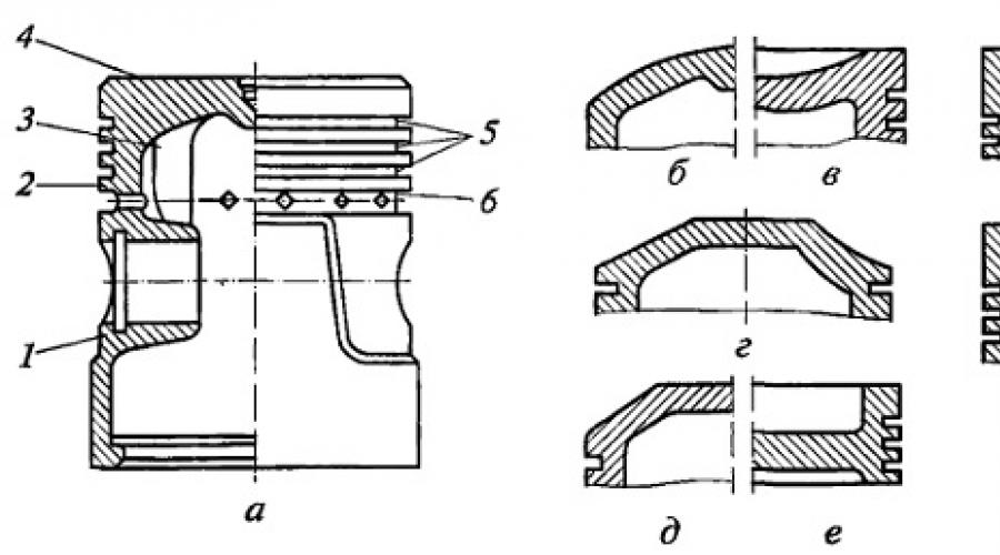
Piston is a metal glass of complex shape, installed in a cylinder with the bottom up. It consists of two main parts. The upper thickened part is called the head, and the lower guide part is called the skirt. The piston head contains a bottom 4 (Fig. a) and walls 2. Grooves 5 for compression rings are machined in the walls. The lower grooves have drainage holes 6 to drain oil. To increase the strength and rigidity of the head, its walls are equipped with massive ribs 3 that connect the walls and bottom with bosses in which the piston pin is installed. Sometimes the inner surface of the bottom is also ribbed.
The skirt has thinner walls than the head. In its middle part there are bosses with holes.

Rice. Designs of pistons with different bottom shapes (a-z) and their elements:
1 - boss; 2 - piston wall; 3 - rib; 4 - piston bottom; 5 - grooves for compression rings; 6 - drainage hole for oil drainage
The piston heads can be flat (see a), convex, concave and shaped (Fig. b-h). Their shape depends on the type of engine and combustion chamber, the adopted mixture formation method and the piston manufacturing technology. The simplest and most technologically advanced is the flat form. Diesel engines use pistons with concave and shaped bottoms (see Fig. e-h).
When the engine is running, the pistons heat up more than cylinders cooled by liquid or air, so the expansion of the pistons (especially aluminum ones) is greater. Despite the presence of a gap between the cylinder and the piston, jamming of the latter may occur. To prevent jamming, the skirt is given an oval shape (the major axis of the oval is perpendicular to the piston pin axis), the diameter of the skirt is increased compared to the diameter of the head, the skirt is cut (most often a T- or U-shaped cut is made), and compensation inserts are poured into the piston to limit thermal expansion skirts in the plane of swing of the connecting rod, or forcefully cool the internal surfaces of the piston with jets of engine oil under pressure.
A piston subjected to significant force and thermal loads must have high strength, thermal conductivity and wear resistance. In order to reduce inertial forces and moments, it must have a low mass. This is taken into account when choosing the design and material for the piston. Most often the material is aluminum alloy or cast iron. Sometimes steel and magnesium alloys are used. Promising materials for pistons or their individual parts are ceramics and sintered materials that have sufficient strength, high wear resistance, low thermal conductivity, low density and a small coefficient of thermal expansion.
Piston rings
Piston rings provide a tight movable connection between the piston and the cylinder. They prevent the breakthrough of gases from the above-piston cavity into the crankcase and the entry of oil into the combustion chamber. There are compression and oil scraper rings.
Compression rings(two or three) are installed in the upper grooves of the piston. They have a cut called a lock and can therefore spring back. In the free state, the diameter of the ring should be slightly larger than the diameter of the cylinder. When such a ring is inserted into the cylinder in a compressed state, it creates a tight connection. In order to ensure that the ring installed in the cylinder can expand when heated, there must be a gap of 0.2...0.4 mm in the lock. In order to ensure good running-in of compression rings, rings with a tapered outer surface, as well as twisting rings with a chamfer on the edge on the inside or outside, are often used on cylinders. Due to the presence of a chamfer, such rings, when installed in a cylinder, are skewed in cross-section, fitting tightly to the walls of the grooves on the piston.
Oil scraper rings(one or two) remove oil from the cylinder walls, preventing it from entering the combustion chamber. They are located on the piston under the compression rings. Typically, oil scraper rings have an annular groove on the outer cylindrical surface and radial through slots to drain oil, which passes through them to the drainage holes in the piston (see Fig. a). In addition to oil scraper rings with slots for oil drainage, composite rings with axial and radial expanders are used.
To prevent gas leakage from the combustion chamber into the crankcase through the locks of the piston rings, it is necessary to ensure that the locks of adjacent rings are not located on the same straight line.
Piston rings operate under difficult conditions. They are exposed to high temperatures, and lubrication of their outer surfaces, moving at high speed along the cylinder mirror, is not enough. Therefore, high demands are placed on the material for piston rings. Most often, high-grade alloy cast iron is used for their manufacture. Upper compression rings, which operate under the most severe conditions, are usually coated on the outside with porous chrome. Composite oil scraper rings are made of alloy steel.
Piston pin
Piston pin serves for a hinged connection of the piston with the connecting rod. It is a tube passing through the upper head of the connecting rod and installed with its ends in the piston bosses. The piston pin is secured to the bosses by two retaining spring rings located in special grooves of the bosses. This fastening allows the finger (in this case it is called a floating one) to rotate. Its entire surface becomes working, and it wears out less. The pin axis in the piston bosses can be shifted relative to the cylinder axis by 1.5...2.0 mm in the direction of the greater lateral force. This reduces piston knock in a cold engine.
Piston pins are made of high quality steel. To ensure high wear resistance, their outer cylindrical surface is hardened or carburized, and then ground and polished.
Piston group consists of a fairly large number of parts (piston, rings, pin), the mass of which can fluctuate for technological reasons; within certain limits. If the difference in the mass of the piston groups in different cylinders is significant, then additional inertial loads will arise during engine operation. Therefore, piston groups for one engine are selected so that they differ insignificantly in weight (for heavy engines by no more than 10 g).
The connecting rod group of the crank mechanism consists of:
- connecting rod
- upper and lower connecting rod heads
- bearings
- connecting rod bolts with nuts and elements for their fixation
connecting rod
connecting rod connects the piston to the crankshaft crank and, transforming the reciprocating motion of the piston group into the rotational motion of the crankshaft, performs a complex movement, while being subjected to alternating shock loads. The connecting rod consists of three structural elements: rod 2, upper (piston) head 1 and lower (crank) head 3. The connecting rod rod usually has an I-section. To reduce friction, a bronze bushing 6 with a hole for supplying oil to the rubbing surfaces is pressed into the upper head to reduce friction. The lower head of the connecting rod is split to allow assembly with the crankshaft. For gasoline engines, the head connector is usually located at an angle of 90° to the axis of the connecting rod. In diesel engines, the lower head of the connecting rod 7, as a rule, has an oblique connector. The lower head cover 4 is attached to the connecting rod with two connecting rod bolts, precisely matched to the holes in the connecting rod and the cover to ensure high precision assembly. To prevent the fastening from loosening, the bolt nuts are secured with cotter pins, lock washers or lock nuts. The hole in the lower head is bored together with the cover, so the connecting rod covers cannot be interchangeable.

Rice. Connecting rod group details:
1 - upper connecting rod head; 2 - rod; 3 - lower head of the connecting rod; 4 - lower head cover; 5 - liners; 6 - bushing; 7 - diesel connecting rod; S - main connecting rod of the articulated connecting rod assembly
To reduce friction in the connection of the connecting rod with the crankshaft and facilitate engine repair, a connecting rod bearing is installed in the lower head of the connecting rod, which is made in the form of two thin-walled steel liners 5 filled with an antifriction alloy. The inner surface of the liners is precisely adjusted to the crankshaft journals. To fix the liners relative to the head, they have bent antennae that fit into the corresponding grooves in the head. The supply of oil to the rubbing surfaces is provided by annular grooves and holes in the liners.
To ensure good balance of the parts of the crank mechanism, the connecting rod groups of one engine (as well as the piston ones) must have the same mass with its corresponding distribution between the upper and lower heads of the connecting rod.
V-twin engines sometimes use articulated connecting rod assemblies, consisting of paired connecting rods. The main connecting rod 8, which has a conventional design, is connected to the piston of one row. An auxiliary trailing connecting rod, connected by the upper head to a piston of another row, is pivotally attached with a pin to the lower head of the main connecting rod by the lower head.
Connected to the piston by means of a connecting rod, it absorbs the forces acting on the piston. A torque is generated on it, which is then transmitted to the transmission, and is also used to drive other mechanisms and units. Under the influence of inertial forces and gas pressure that sharply change in magnitude and direction, the crankshaft rotates unevenly, experiencing torsional vibrations, being subjected to twisting, bending, compression and tension, and also receiving thermal loads. Therefore, it must have sufficient strength, rigidity and wear resistance with a relatively low weight.
Crankshaft designs are complex. Their shape is determined by the number and arrangement of cylinders, the order of operation of the engine and the number of main bearings. The main parts of the crankshaft are main journals 3, connecting rod journals 2, cheeks 4, counterweights 5, front end (toe 1) and rear end (shank 6) with a flange.
The lower heads of the connecting rods are attached to the connecting rod journals of the crankshaft. The main journals of the shaft are installed in the bearings of the engine crankcase. The main and connecting rod journals are connected using cheeks. A smooth transition from the journals to the cheeks, called a fillet, avoids stress concentrations and possible breakdowns of the crankshaft. Counterweights are designed to unload the main bearings from the centrifugal forces that arise on the crankshaft during its rotation. They are usually made as one piece with the cheeks.
To ensure normal engine operation, engine oil must be supplied under pressure to the working surfaces of the main and connecting rod journals. Oil flows from holes in the crankcase to the main bearings. Then it reaches the connecting rod bearings through special channels in the main journals, cheeks and crankpins. For additional centrifugal oil purification, the connecting rod journals have dirt-collecting cavities closed with plugs.
Crankshafts are made by forging or casting from medium-carbon and alloy steels (high-quality cast iron can also be used). After mechanical and thermal treatment, the main and connecting rod journals are subjected to surface hardening (to increase wear resistance), and then ground and polished. After processing, the shaft is balanced, i.e., such a distribution of its mass relative to the axis of rotation is achieved in which the shaft is in a state of indifferent equilibrium.
Main bearings use thin-walled wear-resistant liners similar to the liners of connecting rod bearings. To absorb axial loads and prevent axial displacement of the crankshaft, one of its main bearings (usually the front one) is made thrust.
Flywheel
Flywheel is attached to the crankshaft shank flange. It is a carefully balanced cast iron disk of a certain mass. In addition to ensuring uniform rotation of the crankshaft, the flywheel helps overcome compression resistance in the cylinders when starting the engine and short-term overloads, for example, when starting a vehicle. A ring gear is attached to the flywheel rim to start the engine from the starter. The surface of the flywheel that comes into contact with the clutch driven disc is ground and polished.

Rice. Crankshaft:
1 - sock; 2 - connecting rod journal; 3 - molar neck; 4 - cheek; 5 - counterweight; 6 - shank with flange
The crank mechanism device is designed to convert the reciprocating motion of the piston into rotational motion, which can act as the movement of the crankshaft in an internal combustion engine of a car, and vice versa.
The parts of the crank mechanism are divided into two groups, which include: moving parts and stationary parts. The moving parts are: piston together with, crankshaft device with bearings, connecting rod, piston pin, flywheel and crank. Fixed parts include: cylinder block, which are the basic parts of an internal combustion engine (is a single casting with the crankcase); clutch and flywheel housing, cylinder head, lower crankcase, block covers, cylinder liners, block cover gaskets, fasteners, crankshaft half rings, brackets.
1. Purpose and characteristics of the connecting rod mechanism.

The crank mechanism is the main device of a piston internal combustion engine. This system is designed to perceive gas pressure at a certain stroke. In addition, this mechanism allows you to convert the movements of the reciprocating pistons into rotational movements of the car’s crankshaft.
This standard device consists of pistons that have piston rings, liners and cylinder heads, crankcase, connecting rods, crankshaft, flywheel, connecting rod and main bearings. During the moments of direct operation of the internal combustion engine, the inertial forces of reciprocating moving masses, gas pressure, inertia of various kinds of unbalanced rotating masses, friction and gravity directly affect the parts of the crank mechanism.
All of the above forces, except, of course, gravity, affect the change in the value and direction of all the quantities under consideration. All this directly depends on the angle of rotation of the crankshaft device and the processes that occur directly in the cylinders of the internal combustion engine.
2. Design of the connecting rod mechanism.
Since all the components of the crank mechanism are already known, it is worth starting to consider the crankshaft structure. The crankshaft is one of the main elements of an internal combustion engine, which, along with other parts of the cylinder-piston group, determines the life of the engine itself.
 Thus, the service life of the device will be characterized by several indicators: wear resistance and fatigue strength. The crankshaft takes on all the forces that act on the pistons with the help of connecting rods. After this, the crankshaft transmits all these forces to the transmission mechanism. It will already power various types of internal combustion engine mechanisms. The crankshaft structure consists of: main journals, connecting rod journals, connecting cheeks, a shank and a toe.
3. Malfunctions of the connecting rod mechanism.
During direct operation of an internal combustion engine, as a result of the action of unstable and excessively high dynamic loads, from the inertial forces of moving and rotating parts, from gas pressure, the shaft is subjected to bending and torsion, and individual surfaces of the device simply wear out.
All fatigue damage accumulates directly in the metal structure, resulting in microcracks and various types of defects. The wear of elements is determined by using universal and special measuring tools. In order to detect cracks, you need to use a magnetic flaw detector. With constant use of the crankshaft, it is subject to defects.
 The most common is a wear defect. But many parts of the entire device are subject to wear. When the main journals and connecting rods are worn out, out of ovality and taper, it is necessary to grind to the size required for repair. Applying surfacing coatings, electrical contact welding of tape, metallization, filling the surface with powder materials is the solution to this problem.
In addition, it is recommended to install new half-rings and perform a plastination procedure. In addition, wear can affect the seats that are needed for the timing gear, pulley and flywheel. Wear also affects oil threads, flywheel flange surfaces, flywheel pins, and keyways. In order to solve all the above problems it will not take a lot of resources and time.
For the first problem, you need to perform conventional metallization, surfacing or electronic welding of the tape. The problem with the thread is solved by simply deepening the thread with a cutter to a normalized profile. The pins simply need to be replaced, but for the grooves you need to mill for the increased size of the keys and for new keyways. After this you need to do welding and the problem will disappear.
 In addition, wear can also affect the seat for the outer rings at the end of the shaft, holes for the pins, flywheel mounting and threads. Everywhere you need to bore the seats and press in the bushings. In addition, the pins need to be reamed for repair size and welded. Threading also requires countersinking or boring with enlargement of the thread in a subsequent process. All threaded holes are also deepened.
In addition to wear, problems also arise with shaft twisting, which results in a violation of the position of the cranks. In this case, you need to grind the journals to a special repair size and fuse the journals with subsequent processing. The most problematic can be cracks in the shaft journals, since in addition to grinding them to the repair size, it will be necessary to cut the cracks using an abrasive tool. In principle, this is quite enough for the motorist, since other problems and malfunctions may require professional intervention from outside.
4. Servicing the connecting rod mechanism.
Proper maintenance of the internal combustion engine and its normal operation will ensure minimal wear of all its parts and its uninterrupted operation. In addition, the crank mechanism will not need repair for quite a long time.
 In order to ensure normal operating conditions for all structural components of the crank mechanism during its operation strictly NOT allowed following:
- prolonged operation when the engine is overloaded;
Operating the engine under conditions of low oil pressure;
Operating the engine at very low crankcase oil temperatures;
Prolonged idling of the engine, which will cause coking of the piston rings;
Operation of a motor in which there is no fan casing or there is one, but its fit is loose to the mating surface;
Engine operation where there is no air cleaner or it is in a faulty condition;
Intermittent engine operation, accompanied by smoky exhaust and knocking.
 When directly disassembling the internal combustion engine device for its repair, the cavities of the connecting rod journals of the crankshaft mechanism should be cleaned. In order to completely clean all the cavities, you need to pull out the cotter pins and unscrew the screw plugs. The effective composition of the centrifugal cleaning of oil from the cavities of the connecting rod journals will depend on all the rules for maintaining the lubrication system and on how correctly the oil is stored and refilled into the engine.
If the recommended rules are not followed, then the cavities of the connecting rod journals will quickly fill with various deposits, and oil purification will generally disappear into oblivion. If the power has decreased greatly, the smoke and gases are quite strong, starting the engine is difficult, and abnormal knocking noises occur that are associated with a malfunction of the crank mechanism, you should immediately “get into” the device and inspect it. Disassembly of the internal combustion engine should be done indoors.
Almost any piston engine installed in a car, tractor, walk-behind tractor uses a crank mechanism. They are also used in compressors for producing compressed air. The energy of expanding gases, combustion products of the next portion of the working mixture, is converted by the crank mechanism into rotation of the working shaft, transmitted to the wheels, tracks or drive of the brush cutter. In a compressor, the opposite phenomenon occurs: the rotational energy of the drive shaft is converted into potential energy of air or other gas compressed in the working chamber.
Mechanism design
The first crank devices were invented in the ancient world. In ancient Roman sawmills, the rotational motion of a water wheel, driven by the river current, was transformed into a reciprocating motion of the saw blade. In antiquity, such devices were not widely used for the following reasons:
- wooden parts wore out quickly and required frequent repairs or replacement;
- slave labor was cheaper than high technology for that time.
In a simplified form, the crank mechanism has been used since the 16th century in village spinning wheels. The movement of the pedal was converted into rotation of the spinning wheel and other parts of the device.
Steam engines developed in the 18th century also used a crank mechanism. It was located on the driving wheel of the locomotive. The steam pressure on the piston bottom was converted into the reciprocating movement of a rod connected to a connecting rod pivotally mounted on the drive wheel. The connecting rod gave the wheel rotation. This arrangement of the crank mechanism was the basis of mechanical transport until the first third of the 20th century.
The locomotive design was improved in crosshead engines. The piston in them is rigidly attached to the crosshead rod, which slides back and forth in the guides. A hinge is attached to the end of the rod, and a connecting rod is attached to it. This scheme increases the range of working movements and even makes it possible to make a second chamber on the other side of the piston. Thus, each movement of the rod is accompanied by a working stroke. Such kinematics and dynamics of the crank mechanism make it possible to double the power with the same dimensions. Crossheads are used in large stationary and ship diesel installations.
The elements that make up the crank mechanism are divided into the following types:
- Movable.
- Fixed.
The first include:
- piston;
- rings;
- fingers;
- connecting rod;
- flywheel;
- crankshaft;
- crankshaft plain bearings.
The fixed parts of the crank mechanism include:
- cylinder block;
- sleeve;
- block head;
- brackets;
- crankcase;
- other minor elements.
Pistons, pins and rings are combined into a piston group.
Each element, as well as the detailed kinematic diagram and operating principle, deserves a more detailed consideration
This is one of the most complex engine parts in terms of configuration. The schematic three-dimensional drawing shows that inside it is pierced by two non-intersecting systems of channels for supplying oil to the points of lubrication and coolant circulation. It is cast from cast iron or light metal alloys and contains places for pressing cylinder liners, brackets for crankshaft bearings, space for the flywheel, lubrication and cooling systems. The unit is connected to the pipes for the fuel mixture supply and exhaust gas removal system.
An oil sump-lubricant reservoir is attached to the bottom of the block through a sealed gasket. It is in this crankcase that the main work of the crank mechanism, abbreviated as KShM, takes place.
The liner must withstand the high pressure in the cylinder. It is created by gases formed after combustion of the fuel mixture. Therefore, the place of the block where the liners are pressed must withstand high mechanical and thermal loads.
The sleeves are usually made of durable steel, less often - of cast iron. During engine operation they wear out and can be replaced during a major engine overhaul. There are two main layouts for their placement:
- dry, the outer side of the liner transfers heat to the material of the cylinder block;
- wet, the liner is washed from the outside with coolant.
The second option allows you to develop more power and tolerate peak loads.
Pistons
The part is a steel or aluminum casting in the form of an inverted glass. Sliding along the walls of the cylinder, it takes on the pressure of the burnt fuel mixture and turns it into linear movement. Then, through the crank assembly, it turns into rotation of the crankshaft, and then is transmitted to the clutch and gearbox and through the cardan to the wheels. The forces acting in the crank mechanism set the vehicle or stationary mechanism in motion.
The part performs the following functions:
- on the intake stroke, moving downward (or in the direction from the crankshaft if the cylinder is not located vertically) on, it increases the volume of the working chamber and creates a vacuum in it, drawing in and evenly distributing the next portion of the working mixture throughout the volume;
- on the compression stroke, the piston group moves upward, compressing the working mixture to the required degree;
- Next comes the power stroke, the part under pressure goes down, transmitting a rotational impulse to the crankshaft;
- on the exhaust stroke it goes up again, displacing exhaust gases into the exhaust system.
At all strokes, except for the working stroke, the piston group moves due to the crankshaft, taking away part of the energy of its rotation. On single-cylinder engines, a massive flywheel is used to accumulate such energy; on multi-cylinder engines, the cylinder strokes are shifted in time.
Structurally, the product is divided into the following parts:
- bottom, which absorbs gas pressure;
- seal with grooves for piston rings;
- a skirt in which a finger is secured.
The pin serves as an axis on which the upper arm of the connecting rod is fixed.
Piston rings
The purpose and design of piston rings is determined by their role in the operation of crank devices. The rings are made flat, they have a cut a few tenths of a millimeter wide. They are inserted into the annular grooves machined for them on the seal.
The rings perform the following functions:
- Seal the gap between the liner and the piston walls.
- Provide direction of piston movement.
- Cool. Touching the liner, the compression rings remove excess heat from the piston, protecting it from overheating.
- Isolate the working chamber from lubricants in the crankcase. On the one hand, the rings retain droplets of oil sprayed into the crankcase by the impacts of the counterweights of the crankshaft cheeks; on the other hand, they allow a small amount of oil to pass through to lubricate the cylinder walls. The lower oil scraper ring is responsible for this.
The connection between the piston and connecting rod also needs to be lubricated.
Lack of lubrication within a few minutes renders the cylinder parts unusable. The rubbing parts overheat and begin to break down or become jammed. Repair in this case will be difficult and expensive.
Piston pins
The piston and connecting rod are kinematically connected. The product is fixed in the piston skirt and serves as the axis of the sliding bearing. The parts withstand high dynamic loads during the working stroke, as well as changes in stroke and reversal of the direction of movement. They are machined from high-alloy heat-resistant alloys.
The following types of finger designs are distinguished:
- Fixed. They are fixedly mounted in the skirt, only the cage of the upper part of the connecting rod rotates.
- Floating. They can rotate in their fastenings.
The floating design is used in modern engines; it reduces the specific loads on the components of the crank group and increases their service life.
This critical element of the engine crank mechanism is made dismountable so that the bearing shells in its cages can be changed. Sliding bearings are used on low-speed engines; on high-speed engines, more expensive rolling bearings are installed.
In appearance, the connecting rod resembles a spanner. To increase strength and reduce weight, the cross section is made in the form of an I-beam.
During operation, the part experiences alternate loads of longitudinal compression and tension. For manufacturing, castings from alloy or high-carbon steel are used.
The transformation is carried out with help.
Of the parts of the crank group, the crankshaft has the most complex spatial shape. Several articulated joints move the rotation axes of its segments away from the main longitudinal axis. The lower races of the connecting rods are attached to these remote axles. The physical meaning of the design is exactly the same as when securing the connecting rod axis to the edge of the flywheel. In the crankshaft, the “extra”, unused part of the flywheel is removed and replaced with a counterweight. This allows you to significantly reduce the weight and dimensions of the product and increase the maximum available speed.
The main parts that make up the crankshaft are as follows:
- Shakey. Serve for fastening the shaft in the crankcase brackets and connecting rods on the shaft. The first are called main, the second - connecting rod.
- Cheeks. They form the knees that give the knot its name. Rotating around the longitudinal axis and pushed by connecting rods, they convert the energy of the longitudinal movement of the piston group into rotational energy of the crankshaft.
- Front exit part. A pulley is placed on it, from which the shafts of the auxiliary systems of the engine - cooling, lubrication, distribution mechanism, and generator - rotate using a chain or belt drive.
- Main output part. Transfers energy to the transmission and further to the wheels.
The back part of the cheeks, protruding beyond the axis of rotation of the crankshaft, serves as a counterweight for their main part and the connecting rod journals. This allows you to dynamically balance a structure rotating at high speed, avoiding destructive vibrations during operation.
For the manufacture of crankshafts, castings from light high-strength cast iron or hot stampings (forgings) from hardened steel are used.
Crankcase
It serves as the structural basis of the entire engine; all other parts are attached to it. External brackets extend from it, on which the entire unit is attached to the body. A transmission is attached to the crankcase, transmitting torque from the engine to the wheels. In modern designs, the crankcase is made as a single part with the cylinder block. Within its spatial framework, the main work of the components, mechanisms and parts of the motor takes place. A pan is attached to the bottom of the crankcase to store oil to lubricate the moving parts.
Operating principle of the crank mechanism
The operating principle of the crank mechanism has not changed over the past three centuries.
During the power stroke, the working mixture ignited at the end of the compression stroke quickly burns, the combustion products expand and push the piston down. He pushes the connecting rod, which rests on the lower axis, spaced apart from the main longitudinal axis. As a result, under the influence of tangentially applied forces, the crankshaft rotates a quarter of a turn in four-stroke engines and half a turn in two-stroke engines. Thus, the longitudinal movement of the piston is converted into rotation of the shaft.
Calculation of the crank mechanism requires excellent knowledge of applied mechanics, kinematics, and strength of materials. It is entrusted to the most experienced engineers.
Malfunctions that occur during the operation of the crankshaft and their causes
Malfunctions can occur in different elements of the crank group. The complexity of the design and combination of parameters of engine connecting rod mechanisms makes it necessary to pay special attention to their calculation, manufacture and operation.
Most often, failures result from non-compliance with the operating modes and maintenance of the motor. Poor quality lubrication, clogging of oil supply channels, untimely replacement or replenishment of oil in the crankcase to the specified level - all these reasons lead to increased friction, overheating of parts, and the appearance of scuffs, abrasions and scratches on their working surfaces. The oil filter should be changed every time you change the oil. In accordance with the maintenance schedule, fuel and air filters also need to be changed.
Malfunction of the cooling system also causes thermal deformation of parts, up to their jamming or destruction. Diesel engines are especially sensitive to the quality of lubrication.
Problems in the ignition system can also lead to carbon deposits on the piston and its rings. Coking of the rings causes a decrease in compression and damage to the cylinder walls.
It also happens that the cause of a breakdown is low-quality or counterfeit parts or materials used during maintenance. It is better to purchase them from official dealers or trusted stores that care about their reputation.
List of KShM malfunctions
The most common mechanism failures are:
- wear and destruction of the crankshaft connecting rod and main journals;
- grinding, chipping or melting of plain bearing shells;
- contamination of piston rings by combustion carbon deposits;
- overheating and breakage of rings;
- accumulation of carbon deposits on the piston head leads to its overheating and possible destruction;
- Long-term operation of the engine with detonation effects causes the piston crown to burn out.
The combination of these faults with a malfunction in the lubrication system can cause misalignment of the pistons in the cylinders and engine seizure. Elimination of all these breakdowns involves dismantling the engine and its partial or complete disassembly.
Repairs take a long time and are expensive, so it is better to identify malfunctions in the early stages and correct problems in a timely manner.
Signs of malfunctions in the operation of the crankshaft
For timely detection of failures and negative processes beginning to develop in the crank group, it is useful to know from external signs:
- Knocks in the engine, unusual sounds during acceleration. Ringing sounds are often caused by detonation phenomena. Incomplete combustion of fuel during the power stroke and its explosive combustion during the exhaust stroke lead to the accumulation of carbon deposits on the rings and the piston crown, deterioration of their cooling conditions and destruction. It is necessary to fill in high-quality fuel and check the operating parameters of the ignition system on the stand.
- Dull knocks indicate wear on the crankshaft journals. In this case, you should stop operating, grind the journals and replace the liners with thicker ones from the repair kit.
- A sound that “sings” at a high, loud note indicates the possible beginning of melting of the liners or a lack of oil when the speed increases. You also need to urgently go to the service center.
- Blue clouds of smoke from the exhaust pipe indicate excess oil in the working chamber. The condition of the rings should be checked and replaced if necessary.
- A drop in power can also be caused by ring coking and decreased compression.
If you notice these alarming symptoms, do not postpone your visit to the service center. A seized engine will cost much more, both in money and time.
KShM maintenance
In order not to damage the crankshaft parts, you must comply with all the manufacturer’s requirements for periodic maintenance and regular inspection of the vehicle.
The oil level, especially on a vehicle that is not new, should be checked daily before leaving. It takes less than a minute, and can save months of waiting in the event of a serious breakdown.
Fuel should be filled only from proven gas stations of well-known brands, without being seduced by the two-ruble difference in price.
If you notice the alarming symptoms listed above, you should immediately go to a service station.
You should not try to bore cylinders, remove carbon deposits from rings, or perform other complex repair work on your own, based on videos from the Internet. If you do not have many years of experience in such work, it is better to turn to professionals. Self-installation of the connecting rod mechanism after repair is a very difficult operation.
It is reasonable to use various patented means “to transform carbon deposits on cylinder walls” or “to decarbonize” only when you are absolutely sure of both the diagnosis and the medicine.
You may also be interested in the following articles:
Crank-slider mechanism: device, principle of operation, application
The crank mechanism is the mechanism that carries out the working process of the engine.
The crank mechanism is designed to convert the reciprocating motion of the pistons into the rotational motion of the crankshaft.
The crank mechanism determines the type of engine by the arrangement of the cylinders.
Various crank and connecting rod mechanisms are used in car engines: single-row crank and connecting rod mechanisms with vertical movement of pistons and with angular movement of pistons are used in in-line engines; double-row crank mechanisms with pistons moving at an angle are used in V-shaped engines; Single- and double-row crank mechanisms with horizontal movement of pistons are used in cases where the overall height dimensions of the engine are limited.

Picture 1– Types of crank mechanisms, classified according to various criteria.
Design of the crank mechanism.
The crank mechanism includes a cylinder block with a crankcase and cylinder head, a connecting rod and piston group and a crankshaft with a flywheel.
Cylinder block 11 () with crankcase 10 and cylinder head 8 are fixed parts of the crank mechanism.
The moving parts of the mechanism include the crankshaft 34 with the flywheel 43 and parts of the connecting rod and piston group - pistons 24, piston rings 18 and 19, piston pins 26 and connecting rods 27.

Figure 2– Crank mechanism of passenger car engines
1, 6 – covers; 2 – support; 3, 9 – cavities; 4, 5 – gaskets; 7 – neck; 8, 22, 28, 30 – heads; 10 – crankcase; 11 – cylinder block; 12 – 16, 20 – tides; 17, 33 – holes; 18, 19 – rings; 21 – grooves; 23 – bottom; 24 – piston; 25 – skirt; 26 – finger; 27 – connecting rod; 29 – rod; 31, 42 – bolts; 32, 44 – liners; 34 – crankshaft; 35, 40 – ends of the crankshaft; 36, 38 – necks; 37 – cheek; 39 – counterweight; 41 – washer; 43 – flywheel; 45 – half ring
Cylinder block together with crankcase is the core of the engine. Engine mechanisms and devices are located on it and inside it. In block 11, made integral with crankcase 10 from special low-alloy cast iron, the engine cylinders are made. The internal surfaces of the cylinders are ground and are called the cylinder surface. Inside the block between the cylinder walls and its outer walls there is a special cavity 9, called the cooling jacket. It circulates the coolant of the engine cooling system.
Inside the block there are also channels and an oil line for the lubrication system, through which oil is supplied to the rubbing parts of the engine. At the bottom of the cylinder block (in the crankcase) there are supports 2 for the crankshaft main bearings, which have removable covers 1 attached to the block with self-locking bolts. In the front part of the block there is a cavity 3 for the chain drive of the gas distribution mechanism. This cavity is closed by a lid cast from an aluminum alloy. On the left side of the cylinder block there are holes 17 for the bearings of the oil pump drive shaft, into which rolled steel-aluminum bushings are pressed. On the right side of the block in the front part there is a flange for installing a coolant pump and a bracket for mounting the generator. The cylinder block has special bosses for: 12 – fastening the engine mount brackets; 13 – oil separator for the crankcase ventilation system; 14 – fuel pump; 15 – oil filter; 16 – ignition distributor. The bottom of the cylinder block is covered with an oil pan, and the clutch housing is attached to its rear end. To increase rigidity, the lower plane of the cylinder block is slightly lowered relative to the axis of the crankshaft.
In contrast to the block cast together with the cylinders, a block of 4 cylinders with a crankcase 5 is presented, cast from an aluminum alloy separately from the cylinders. The cylinders are easily removable cast iron liners 2, installed in the sockets 6 of the block with sealing rings 1 and closed on top by the block head with a sealing gasket.

Figure 3
1 – ring; 2 – sleeve; 3 – cavity; 4 – block; 5 – crankcase; 6 – socket
The inner surface of the sleeves is processed by grinding. To reduce wear, inserts made of special cast iron are installed in the upper part of the liners.
Removable cylinder liners increase engine durability and simplify assembly, operation and repair.
Between the outer surface of the cylinder liners and the inner walls of the block there is a cavity 3, which is the engine cooling jacket. Coolant circulates in it, washing the cylinder liners, which are called wet due to contact with the liquid.
Cylinder head closes the cylinders from above and serves to house the combustion chambers, valve mechanism and channels for supplying the combustible mixture and removing exhaust gases. The cylinder head 8 (see) is made common to all cylinders, cast from aluminum alloy and has wedge-shaped combustion chambers. It has a cooling jacket and threaded holes for spark plugs. Seats and valve guides made of cast iron are pressed into the head. The head is attached to the cylinder block with bolts. A metal-asbestos gasket 4 is installed between the head and the cylinder block, ensuring the tightness of their connection. A bearing housing with a camshaft is attached to the top of the cylinder head with studs, and it is closed with a stamped steel cap 6 with a neck 7 for pouring oil into the engine. To eliminate oil leakage, a sealing gasket 5 is installed between the cover and the cylinder head. On the right side, the intake and exhaust pipelines, cast from aluminum alloy and cast iron respectively, are attached to the cylinder head with studs through a metal-asbestos gasket.
Piston serves to perceive gas pressure during the working stroke and carry out auxiliary strokes (intake, compression, exhaust). The piston 24 is a hollow cylinder cast from an aluminum alloy. It has a bottom 23, a head 22 and a skirt 25. The bottom of the piston bottom is reinforced with ribs. The piston head has grooves 21 for piston rings.
In the piston skirt there are bosses 20 (bosses) with holes for the piston pin. The piston bosses are filled with steel thermal compensation plates, which reduce the expansion of the piston from heating and prevent it from jamming in the engine cylinder. The skirt is made oval in cross section, conical in height and with cutouts in the lower part. The ovality and taper of the skirt, as well as the temperature compensation plates, prevent jamming of the piston, and the cutouts prevent the piston from touching the crankshaft counterweights. In addition, cutouts in the skirt reduce the mass of the piston. For better running-in to the cylinder, the outer surface of the piston skirt is coated with a thin layer of tin. The hole in the bosses for the piston pin is offset relative to the center plane of the piston. This reduces distortion and shock when passing through top dead center (TDC).
The pistons of passenger car engines can have bottoms of various configurations in order to form combustion chambers of the required shape together with the inner surface of the cylinder head. The piston heads can be flat, convex, concave or with shaped recesses.
Piston rings seal the cylinder cavity, preventing gases from leaking into the engine crankcase (compression 19) and oil from entering the combustion chamber (oil scraper 18). In addition, they remove heat from the piston head to the cylinder walls. Compression and oil scraper rings are split. They are made of special cast iron. Due to their elasticity, the rings fit tightly to the walls of the cylinder. In this case, a small gap (0.2...0.35 mm) remains between the cut ends of the rings (in the locks).
The top compression ring, which operates in the most severe conditions, has a barrel-shaped cross-section to improve its running-in. Its outer surface is chrome plated to increase wear resistance.
The lower compression ring has a scraper-type cross-section (there is a groove on its outer surface) and is phosphated. In addition to the main function, it also performs an additional function - the oil release ring.
The oil scraper ring on the outer surface has a groove and slots for draining oil removed from the cylinder walls into the internal cavity of the piston. On the inner surface it has a groove in which an expansion coil spring is installed, which provides additional compression of the ring to the walls of the engine cylinder.
Piston pin serves to articulate the piston with the upper head of the connecting rod. Finger 26 – tubular, steel. To increase hardness and wear resistance, its outer surface is carburized and hardened with high frequency currents. The pin is pressed into the upper head of the connecting rod with an interference fit, which prevents its axial movement in the piston, which could result in damage to the cylinder walls. The piston pin rotates freely in the piston bosses.
connecting rod serves to connect the piston to the crankshaft and transmit forces between them. Connecting rod 27 is steel, forged, consists of a one-piece upper head 28, an I-section rod 29 and a detachable lower head 30. The lower head connects the connecting rod to the crankshaft. The removable half of the lower head is the cover of the connecting rod and is attached to it with two bolts 31. Thin-walled bimetallic, steel-aluminum liners 32 of the connecting rod bearing are inserted into the lower head of the connecting rod. In the lower head of the connecting rod there is a special hole 33 for lubricating the cylinder walls.
Crankshaft receives forces from the connecting rods and transmits the torque created on it to the vehicle transmission. It also drives various engine mechanisms (gas distribution mechanism, oil pump, ignition distributor, coolant pump, etc.).
Crankshaft 34 is five-bearing, cast from special high-strength cast iron. It consists of main 35 and connecting rod 38 journals, 37 cheeks, 39 counterweights, front 35 and rear 40 ends. The main journals of the crankshaft are installed in bearings (main bearings) of the engine crankcase, the liners 44 of which are thin-walled, bimetallic, steel-aluminium.
The lower heads of the connecting rods are attached to the connecting rod journals of the crankshaft. Connecting rod bearings are lubricated through channels connecting the main journals to the connecting rods. The cheeks connect the main and connecting rod journals of the crankshaft, and the counterweights unload the main bearings from the centrifugal forces of unbalanced masses.
At the front end of the crankshaft are mounted: the drive sprocket of the timing chain drive; belt drive pulley for driving a fan, coolant pump, generator; a ratchet for turning the shaft manually using a starting handle. At the rear end of the crankshaft there is a special socket for installing the bearing of the primary (drive) shaft of the gearbox. The flywheel 43 is attached to the end of the rear end of the shaft using a special washer 41 with bolts 42.
The crankshaft is secured against axial movements by two support half-rings 45, which are installed in the engine cylinder block on both sides of the rear main bearing. Moreover, a steel-aluminum ring is placed on the front side of the bearing, and on the rear side - made of sintered materials (metal-ceramic).
Flywheel ensures uniform rotation of the crankshaft, accumulates energy during the working stroke to rotate the shaft during preparatory strokes and removes the parts of the crank mechanism from dead spots. The energy accumulated by the flywheel makes it easier to start the engine and ensures the vehicle starts moving. Flywheel 43 is a massive disc cast from cast iron. A steel ring gear is pressed onto the flywheel rim, designed to start the engine with an electric starter. The clutch parts are attached to the flywheel. The flywheel, being a part of the crank mechanism, is also one of the leading parts of the clutch.
The crank mechanism is designed to convert the reciprocating motion of the piston into the rotational motion of the crankshaft.
The parts of the crank mechanism can be divided into:
- stationary - crankcase, cylinder block, cylinders, cylinder head, head gasket and pan. Typically the cylinder block is cast together with the upper half of the crankcase, which is why it is sometimes called a block crankcase.
- moving parts of the crankshaft - pistons, piston rings and pins, connecting rods, crankshaft and flywheel.
In addition, the crank mechanism includes various fasteners, as well as main and connecting rod bearings.
Block crankcase
Block crankcase- the main element of the engine frame. It is subject to significant force and thermal influences and must have high strength and rigidity. The crankcase contains cylinders, crankshaft supports, some gas distribution mechanism devices, various components of the lubrication system with its complex network of channels and other auxiliary equipment. The crankcase is made of cast iron or aluminum alloy by casting.
Cylinder
Cylinders are guide elements ⭐ of the crank mechanism. Pistons move inside them. The length of the cylinder generatrix is determined by the stroke of the piston and its dimensions. Cylinders operate under conditions of sharply changing pressure in the above-piston cavity. Their walls come into contact with flames and hot gases with temperatures up to 1500... 2500 °C.
Cylinders must be strong, rigid, heat and wear resistant with limited lubrication. In addition, the cylinder material must have good casting properties and be easy to machine. Typically, cylinders are made from special alloy cast iron, but aluminum alloys and steel can also be used. The inner working surface of the cylinder, called its mirror, is carefully processed and plated with chrome to reduce friction, increase wear resistance and durability.
In liquid-cooled engines, the cylinders may be cast together with the cylinder block or as separate liners installed in the block bores. Between the outer walls of the cylinders and the block there are cavities called a cooling jacket. The latter is filled with liquid that cools the engine. If the cylinder liner is in direct contact with the coolant with its outer surface, then it is called wet. Otherwise it is called dry. The use of replaceable wet liners makes engine repair easier. When installed in a block, wet liners are reliably sealed.
Air-cooled engine cylinders are cast individually. To improve heat dissipation, their outer surfaces are equipped with annular fins. On most air-cooled engines, the cylinders and their heads are secured with common bolts or studs to the top of the crankcase.
In a V-shaped engine, the cylinders of one row may be slightly offset relative to the cylinders of the other row. This is due to the fact that two connecting rods are attached to each crankshaft crank, one of which is intended for the piston of the right half of the block, and the other for the piston of the left half of the block.
Cylinder block
A cylinder head is installed on the carefully processed upper plane of the cylinder block, which closes the cylinders from above. In the head above the cylinders there are recesses that form combustion chambers. For liquid-cooled engines, a cooling jacket is provided in the body of the cylinder head, which communicates with the cooling jacket of the cylinder block. With the valves located at the top, the head has seats for them, inlet and outlet channels, threaded holes for installing spark plugs (for gasoline engines) or injectors (for diesel engines), lubrication system lines, mounting and other auxiliary holes. The material for the block head is usually aluminum alloy or cast iron.
A tight connection between the cylinder block and the cylinder head is ensured using bolts or studs with nuts. To seal the joint in order to prevent leakage of gases from the cylinders and coolant from the cooling jacket, a gasket is installed between the cylinder block and the cylinder head. It is usually made of asbestos cardboard and lined with thin steel or copper sheet. Sometimes the gasket is rubbed with graphite on both sides to protect it from sticking.
The lower part of the crankcase, which protects the parts of the crank and other engine mechanisms from contamination, is usually called the sump. In relatively low-power engines, the pan also serves as a reservoir for engine oil. The pallet is most often cast or made from steel sheet by stamping. To eliminate oil leakage, a gasket is installed between the crankcase and the sump (on low-power engines, a sealant - “liquid gasket”) is often used to seal this joint.
Engine frame
The fixed parts of the crank mechanism connected to each other are the core of the engine, which absorbs all the main power and thermal loads, both internal (related to the operation of the engine) and external (due to the transmission and chassis). The force loads transmitted to the engine frame from the vehicle's supporting system (frame, body, housing) and back significantly depend on the method of engine mounting. Usually it is attached at three or four points so that loads caused by distortions of the supporting system that occur when the machine moves over uneven surfaces are not taken into account. The engine mounting must exclude the possibility of its displacement in the horizontal plane under the influence of longitudinal and transverse forces (during acceleration, braking, turning, etc.). To reduce vibration transmitted to the supporting system of the vehicle from a running engine, rubber cushions of various designs are installed between the engine and the sub-engine frame at the mounting points.
The piston group of the crank mechanism is formed by piston assembly with a set of compression and oil scraper rings, piston pin and its fastening parts. Its purpose is to perceive gas pressure during the power stroke and transmit force to the crankshaft through the connecting rod, carry out other auxiliary strokes, and also seal the above-piston cavity of the cylinder to prevent gases from breaking through into the crankcase and the penetration of engine oil into it.
Piston
Piston is a metal glass of complex shape, installed in a cylinder with the bottom up. It consists of two main parts. The upper thickened part is called the head, and the lower guide part is called the skirt. The piston head contains a bottom 4 (Fig. a) and walls 2. Grooves 5 for compression rings are machined in the walls. The lower grooves have drainage holes 6 to drain oil. To increase the strength and rigidity of the head, its walls are equipped with massive ribs 3 that connect the walls and bottom with bosses in which the piston pin is installed. Sometimes the inner surface of the bottom is also ribbed.
The skirt has thinner walls than the head. In its middle part there are bosses with holes.
Rice. Designs of pistons with different bottom shapes (a-z) and their elements:
1 - boss; 2 - piston wall; 3 - rib; 4 - piston bottom; 5 - grooves for compression rings; 6 - drainage hole for oil drainage
The piston heads can be flat (see a), convex, concave and shaped (Fig. b-h). Their shape depends on the type of engine and combustion chamber, the adopted mixture formation method and the piston manufacturing technology. The simplest and most technologically advanced is the flat form. Diesel engines use pistons with concave and shaped bottoms (see Fig. e-h).
When the engine is running, the pistons heat up more than cylinders cooled by liquid or air, so the expansion of the pistons (especially aluminum ones) is greater. Despite the presence of a gap between the cylinder and the piston, jamming of the latter may occur. To prevent jamming, the skirt is given an oval shape (the major axis of the oval is perpendicular to the piston pin axis), the diameter of the skirt is increased compared to the diameter of the head, the skirt is cut (most often a T- or U-shaped cut is made), and compensation inserts are poured into the piston to limit thermal expansion skirts in the plane of swing of the connecting rod, or forcefully cool the internal surfaces of the piston with jets of engine oil under pressure.
A piston subjected to significant force and thermal loads must have high strength, thermal conductivity and wear resistance. In order to reduce inertial forces and moments, it must have a low mass. This is taken into account when choosing the design and material for the piston. Most often the material is aluminum alloy or cast iron. Sometimes steel and magnesium alloys are used. Promising materials for pistons or their individual parts are ceramics and sintered materials that have sufficient strength, high wear resistance, low thermal conductivity, low density and a small coefficient of thermal expansion.
Piston rings
Piston rings provide a tight movable connection between the piston and the cylinder. They prevent the breakthrough of gases from the above-piston cavity into the crankcase and the entry of oil into the combustion chamber. There are compression and oil scraper rings.
Compression rings(two or three) are installed in the upper grooves of the piston. They have a cut called a lock and can therefore spring back. In the free state, the diameter of the ring should be slightly larger than the diameter of the cylinder. When such a ring is inserted into the cylinder in a compressed state, it creates a tight connection. In order to ensure that the ring installed in the cylinder can expand when heated, there must be a gap of 0.2...0.4 mm in the lock. In order to ensure good running-in of compression rings, rings with a tapered outer surface, as well as twisting rings with a chamfer on the edge on the inside or outside, are often used on cylinders. Due to the presence of a chamfer, such rings, when installed in a cylinder, are skewed in cross-section, fitting tightly to the walls of the grooves on the piston.
Oil scraper rings(one or two) remove oil from the cylinder walls, preventing it from entering the combustion chamber. They are located on the piston under the compression rings. Typically, oil scraper rings have an annular groove on the outer cylindrical surface and radial through slots to drain oil, which passes through them to the drainage holes in the piston (see Fig. a). In addition to oil scraper rings with slots for oil drainage, composite rings with axial and radial expanders are used.
To prevent gas leakage from the combustion chamber into the crankcase through the locks of the piston rings, it is necessary to ensure that the locks of adjacent rings are not located on the same straight line.
Piston rings operate under difficult conditions. They are exposed to high temperatures, and lubrication of their outer surfaces, moving at high speed along the cylinder mirror, is not enough. Therefore, high demands are placed on the material for piston rings. Most often, high-grade alloy cast iron is used for their manufacture. Upper compression rings, which operate under the most severe conditions, are usually coated on the outside with porous chrome. Composite oil scraper rings are made of alloy steel.
Piston pin
Piston pin serves for a hinged connection of the piston with the connecting rod. It is a tube passing through the upper head of the connecting rod and installed with its ends in the piston bosses. The piston pin is secured to the bosses by two retaining spring rings located in special grooves of the bosses. This fastening allows the finger (in this case it is called a floating one) to rotate. Its entire surface becomes working, and it wears out less. The pin axis in the piston bosses can be shifted relative to the cylinder axis by 1.5...2.0 mm in the direction of the greater lateral force. This reduces piston knock in a cold engine.
Piston pins are made of high quality steel. To ensure high wear resistance, their outer cylindrical surface is hardened or carburized, and then ground and polished.
Piston group consists of a fairly large number of parts (piston, rings, pin), the mass of which can fluctuate for technological reasons; within certain limits. If the difference in the mass of the piston groups in different cylinders is significant, then additional inertial loads will arise during engine operation. Therefore, piston groups for one engine are selected so that they differ insignificantly in weight (for heavy engines by no more than 10 g).
The connecting rod group of the crank mechanism consists of:
- connecting rod
- upper and lower connecting rod heads
- bearings
- connecting rod bolts with nuts and elements for their fixation
connecting rod
connecting rod connects the piston to the crankshaft crank and, transforming the reciprocating motion of the piston group into the rotational motion of the crankshaft, performs a complex movement, while being subjected to alternating shock loads. The connecting rod consists of three structural elements: rod 2, upper (piston) head 1 and lower (crank) head 3. The connecting rod rod usually has an I-section. To reduce friction, a bronze bushing 6 with a hole for supplying oil to the rubbing surfaces is pressed into the upper head to reduce friction. The lower head of the connecting rod is split to allow assembly with the crankshaft. For gasoline engines, the head connector is usually located at an angle of 90° to the axis of the connecting rod. In diesel engines, the lower head of the connecting rod 7, as a rule, has an oblique connector. The lower head cover 4 is attached to the connecting rod with two connecting rod bolts, precisely matched to the holes in the connecting rod and the cover to ensure high precision assembly. To prevent the fastening from loosening, the bolt nuts are secured with cotter pins, lock washers or lock nuts. The hole in the lower head is bored together with the cover, so the connecting rod covers cannot be interchangeable.
Rice. Connecting rod group details:
1 - upper connecting rod head; 2 - rod; 3 - lower head of the connecting rod; 4 - lower head cover; 5 - liners; 6 - bushing; 7 - diesel connecting rod; S - main connecting rod of the articulated connecting rod assembly
To reduce friction in the connection of the connecting rod with the crankshaft and facilitate engine repair, a connecting rod bearing is installed in the lower head of the connecting rod, which is made in the form of two thin-walled steel liners 5 filled with an antifriction alloy. The inner surface of the liners is precisely adjusted to the crankshaft journals. To fix the liners relative to the head, they have bent antennae that fit into the corresponding grooves in the head. The supply of oil to the rubbing surfaces is provided by annular grooves and holes in the liners.
To ensure good balance of the parts of the crank mechanism, the connecting rod groups of one engine (as well as the piston ones) must have the same mass with its corresponding distribution between the upper and lower heads of the connecting rod.
V-twin engines sometimes use articulated connecting rod assemblies, consisting of paired connecting rods. The main connecting rod 8, which has a conventional design, is connected to the piston of one row. An auxiliary trailing connecting rod, connected by the upper head to a piston of another row, is pivotally attached with a pin to the lower head of the main connecting rod by the lower head.
Connected to the piston by means of a connecting rod, it absorbs the forces acting on the piston. A torque is generated on it, which is then transmitted to the transmission, and is also used to drive other mechanisms and units. Under the influence of inertial forces and gas pressure that sharply change in magnitude and direction, the crankshaft rotates unevenly, experiencing torsional vibrations, being subjected to twisting, bending, compression and tension, and also receiving thermal loads. Therefore, it must have sufficient strength, rigidity and wear resistance with a relatively low weight.
Crankshaft designs are complex. Their shape is determined by the number and arrangement of cylinders, the order of operation of the engine and the number of main bearings. The main parts of the crankshaft are main journals 3, connecting rod journals 2, cheeks 4, counterweights 5, front end (toe 1) and rear end (shank 6) with a flange.
The lower heads of the connecting rods are attached to the connecting rod journals of the crankshaft. The main journals of the shaft are installed in the bearings of the engine crankcase. The main and connecting rod journals are connected using cheeks. A smooth transition from the journals to the cheeks, called a fillet, avoids stress concentrations and possible breakdowns of the crankshaft. Counterweights are designed to unload the main bearings from the centrifugal forces that arise on the crankshaft during its rotation. They are usually made as one piece with the cheeks.
To ensure normal engine operation, engine oil must be supplied under pressure to the working surfaces of the main and connecting rod journals. Oil flows from holes in the crankcase to the main bearings. Then it reaches the connecting rod bearings through special channels in the main journals, cheeks and crankpins. For additional centrifugal oil purification, the connecting rod journals have dirt-collecting cavities closed with plugs.
Crankshafts are made by forging or casting from medium-carbon and alloy steels (high-quality cast iron can also be used). After mechanical and thermal treatment, the main and connecting rod journals are subjected to surface hardening (to increase wear resistance), and then ground and polished. After processing, the shaft is balanced, i.e., such a distribution of its mass relative to the axis of rotation is achieved in which the shaft is in a state of indifferent equilibrium.
Main bearings use thin-walled wear-resistant liners similar to the liners of connecting rod bearings. To absorb axial loads and prevent axial displacement of the crankshaft, one of its main bearings (usually the front one) is made thrust.
Flywheel
Flywheel is attached to the crankshaft shank flange. It is a carefully balanced cast iron disk of a certain mass. In addition to ensuring uniform rotation of the crankshaft, the flywheel helps overcome compression resistance in the cylinders when starting the engine and short-term overloads, for example, when starting a vehicle. A ring gear is attached to the flywheel rim to start the engine from the starter. The surface of the flywheel that comes into contact with the clutch driven disc is ground and polished.
Rice. Crankshaft:
1 - sock; 2 - connecting rod journal; 3 - molar neck; 4 - cheek; 5 - counterweight; 6 - shank with flange