Lm317t description of characteristics switching diagram. LM317 adjustable voltage and current stabilizer. Characteristics, online calculator, datasheet. Device power dissipation and input voltage
Recently, interest in current stabilizer circuits has grown significantly. And first of all, this is due to the emergence of artificial lighting sources based on LEDs as leading positions, for which a stable current supply is a vital point. The simplest, cheapest, but at the same time powerful and reliable current stabilizer can be built on the basis of one of the integrated circuits (IM): lm317, lm338 or lm350.
Datasheet for lm317, lm350, lm338
Before moving directly to the circuits, let's consider the features and technical characteristics of the above linear integrated stabilizers (LIS).
All three IMs have a similar architecture and are designed to build on their basis simple current or voltage stabilizer circuits, including those used with LEDs. The differences between the microcircuits lie in the technical parameters, which are presented in the comparison table below.
| LM317 | LM350 | LM338 | |
|---|---|---|---|
| Adjustable output voltage range | 1.2…37V | 1.2…33V | 1.2…33V |
| Maximum current load | 1.5A | 3A | 5A |
| Maximum permissible input voltage | 40V | 35V | 35V |
| Indicator of possible stabilization error | ~0,1% | ~0,1% | ~0,1% |
| Maximum power dissipation* | 15-20 W | 20-50 W | 25-50 W |
| Operating temperature range | 0° - 125°С | 0° - 125°С | 0° - 125°С |
| Datasheet | LM317.pdf | LM350.pdf | LM338.pdf |
* - depends on the manufacturer of the IM.
All three microcircuits have built-in protection against overheating, overload and possible short circuit.
Integrated stabilizers (IS) are produced in a monolithic package of several variants, the most common being TO-220. The microcircuit has three outputs:
- ADJUST. Pin for setting (adjusting) the output voltage. In current stabilization mode, it is connected to the positive of the output contact.
- OUTPUT. A pin with low internal resistance to generate output voltage.
- INPUT. Output for supply voltage.
Schemes and calculations
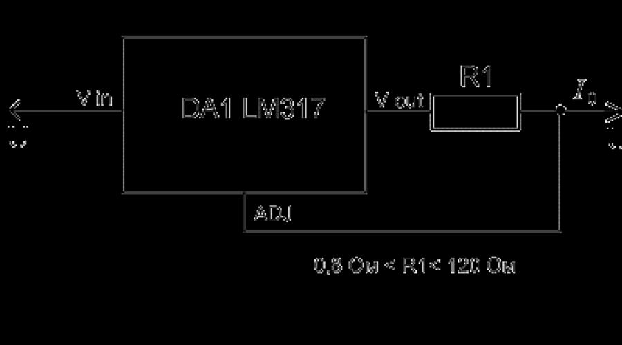
The greatest application of ICs is found in power supplies for LEDs. Let's consider the simplest current stabilizer (driver) circuit, consisting of only two components: a microcircuit and a resistor.  The voltage of the power source is supplied to the input of the MI, the control contact is connected to the output contact through a resistor (R), and the output contact of the microcircuit is connected to the anode of the LED.
If we consider the most popular IM, Lm317t, then the resistor resistance is calculated using the formula: R = 1.25/I 0 (1), where I 0 is the output current of the stabilizer, the value of which is regulated by the passport data for LM317 and should be in the range of 0.01 -1.5 A. It follows that the resistor resistance can be in the range of 0.8-120 Ohms. The power dissipated by the resistor is calculated by the formula: P R =I 0 2 ×R (2). Switching on and calculating IM lm350, lm338 are completely similar.
The resulting calculated data for the resistor is rounded up, according to the nominal series.
Fixed resistors are manufactured with a small variation in resistance value, so it is not always possible to obtain the desired output current value. For this purpose, an additional trimming resistor of appropriate power is installed in the circuit.  This slightly increases the cost of assembling the stabilizer, but ensures that the necessary current is obtained to power the LED. When the output current stabilizes at more than 20% of the maximum value, a lot of heat is generated on the microcircuit, so it must be equipped with a heatsink.
Online calculator lm317, lm350 and lm338
power unit - This is an indispensable attribute in the amateur radio workshop. I also decided to build myself an adjustable power supply, because I was tired of buying batteries every time or using random adapters. Here is its brief description: The power supply regulates the output voltage from 1.2 Volts to 28 Volts. And it provides a load of up to 3 A (depending on the transformer), which is most often enough to test the functionality of amateur radio designs. The circuit is simple, just right for a novice radio amateur. Assembled on the basis of cheap components - LM317 And KT819G.LM317 regulated power supply circuit
List of circuit elements:
- Stabilizer LM317
- T1 - transistor KT819G
- Tr1 - power transformer
- F1 - fuse 0.5A 250V
- Br1 - diode bridge
- D1 - diode 1N5400
- LED1 - LED of any color
- C1 - electrolytic capacitor 3300 uF*43V
- C2 - ceramic capacitor 0.1 uF
- C3 - electrolytic capacitor 1 µF * 43V
- R1 - resistance 18K
- R2 - resistance 220 Ohm
- R3 - resistance 0.1 Ohm*2W
- P1 - construction resistance 4.7K
Pinout of the microcircuit and transistor

The case was taken from the computer's power supply. The front panel is made of PCB, it is advisable to install a voltmeter on this panel. I haven't installed it because I haven't found a suitable one yet. I also installed clamps for the output wires on the front panel.


I left the input socket to power the power supply itself. A printed circuit board made for surface-mounted mounting of a transistor and a stabilizer chip. They were secured to a common radiator through a rubber gasket. The radiator was solid (you can see it in the photo). It needs to be taken as large as possible - for good cooling. Still, 3 amperes is a lot!

Vin (input voltage): 3-40 Volts
Vout (output voltage): 1.25-37 Volts
Output current: up to 1.5 Amps
Maximum power dissipation: 20 Watt
Formula to calculate output (Vout) voltage: Vout = 1.25 * (1 + R2/R1)
*Resistance in Ohms
*Voltage values are obtained in Volts
This simple circuit allows you to rectify alternating voltage into direct voltage thanks to a diode bridge made of diodes VD1-VD4, and then use an accurate substring resistor of the SP-3 type to set the voltage you need within the limits of the integrated stabilizer chip.
I used old ones as rectifier diodes FR3002, which once upon a time fell out of an ancient computer from the year 1998. Despite their impressive size (DO-201AD housing), their characteristics (Ureverse: 100 Volts; Idirect: 3 Amps) are not impressive, but that’s enough for me. For them, we even had to widen the holes in the board, their pins are too thick (1.3mm). If you slightly change the board in the layout, you can immediately solder a ready-made diode bridge.
A radiator to remove heat from the 317 chip is required; it’s even better to install a small fan. Also, at the junction of the TO-220 chip case substrate with the heatsink, drop a little thermal paste. The degree of heating will depend on how much power the chip dissipates, as well as on the load itself.
Microcircuit LM317T I did not install it directly on the board, but brought out three wires from it, with the help of which I connected this component with the others. This was done so that the legs would not become loose and, as a result, would not be broken, because this part will be attached to the heat dissipator.
To be able to use the full voltage of the microcircuit, that is, adjust from 1.25 and right up to 37 Volts, we set the substring resistor with a maximum resistance of 3432 kOhm (in the store the closest value is 3.3 kOhm). Recommended type of resistor R2: interlinear multi-turn (3296).
The LM317T stabilizer chip itself and others like it are produced by many, if not all, companies producing electronic components. Buy only from trusted sellers, because there are Chinese counterfeits, especially often the LM317HV microcircuit, which is designed for an input voltage of up to 57 Volts. You can identify a fake microcircuit by its iron backing; in a fake, it has a lot of scratches and an unpleasant gray color, as well as incorrect markings. It should also be said that the microcircuit has protection against short circuits and overheating, but don’t count on them too much.
Do not forget that this (LM317T) integrated stabilizer is capable of dissipating power with a radiator only up to 20 Watts. The advantages of this common microcircuit are its low price, limitation of internal short circuit current, internal thermal protection
The scarf can be drawn with high quality even with an ordinary parchment marker, and then etched in a solution of copper sulfate/ferric chloride...
Photo of the finished board.
The LM317 linear integrated stabilizer circuit with adjustable output voltage was developed by the author of the first monolithic three-terminal stabilizers, R. Widlar, almost 50 years ago. The microcircuit turned out to be so successful that it is currently produced without changes by all major manufacturers of electronic components and is used in a variety of devices in different connection options.
general information
The circuitry of the device provides higher parameters for instability of parameters, in comparison with stabilizers for a fixed voltage, and has almost all types of protection used for integrated circuits: limiting the output current, shutting down when overheating and exceeding the maximum operating parameters.
At the same time, a minimum number of external components is required for the LM317; the circuit uses built-in stabilization and protection.
The device is available in three versions -L.M.117/217/317, differing in maximum permissible operating temperature:
- LM117: from -55 to 150 °C;
- LM217: from -25 to 150 °C;
- LM317: from 0 to 125 °C.
All types of stabilizers are produced in standard TO-3 housings, various modifications of TO-220, for surface mounting - D2PAK, SO-8. For low power devices, TO-92 is used.
The pinout for all three-pin products is the same, which makes them easier to replace. Depending on the housing used, additional designations are introduced into the markings:
- K – TO-3 (LM317K);
- T – TO-220;
- P – ISOWATT220 (plastic body);
- D2T – D2PAK;
- LZ – TO-92;
- LM – SOIC8.
All standard sizes are used for LM317, LM117 is available only in TO-3 housing, LM217 in TO-3, D2PAK and TO-220. LM317LZ microcircuits in TO-92 packages are distinguished by reduced values of maximum power and output current, up to 100 mA, with similar other properties. Sometimes the manufacturer uses its own markings, for example, LM317НV from Texas Instruments - high-voltage regulators in the range of 1.2-60 V, while the housing pinouts coincide with products from other companies. Unlike other microcircuits, the abbreviation LM (LM) is used by all manufacturers. Explanation of other possible designations is given in the technical description of the specific device.
Basic electrical parametersL.M.117/217/317
The characteristics of the regulators are determined by the difference between the input (Ui) and output voltage (Uo) 5 volts, load current 1.5 amperes and maximum power 20 watts:
- Voltage instability – 0.01%;
- Reference voltage (UREF) – 1.25 V;
- Minimum load current – 3.5 mA;
- The maximum output current is 2.2 A, with a difference in input and output voltages of no more than 15 V;
- The maximum power dissipation is limited by the internal circuitry;
- Input voltage ripple suppression – 80 dB.
It is important to note! At the maximum possible value of Uin – Uout = 40 volts, the permissible load current is reduced to 0.4 amperes. The maximum power dissipation is limited by the internal protection circuit; for TO-220 and TO-3 cases it is approximately 15 to 20 watts.
Applications of Adjustable Stabilizer
When designing electronic devices containing voltage stabilizers, it is more preferable to use a voltage regulator on the LM317, especially for critical equipment components. The use of such solutions requires the additional installation of two resistors, but provides better power parameters than traditional microcircuits with fixed stabilization voltages and has greater flexibility for different applications.

The output voltage is calculated using the formula:
UOUT = UREF (1+ R2/R1) + IADJ, where:
- VREF = 1.25V, control output current;
- IADJ is very small - about 100 µA and determines the voltage setting error, in most cases it is not taken into account.
The input capacitor (ceramic or tantalum 1 μF) is installed at a significant distance from the power supply filter capacitance microcircuit - more than 50 mm; the output capacitor is used to reduce the influence of transient processes at high frequencies; for many applications it is not necessary. The switching circuit uses only one adjustment element - a variable resistor; in practice, a multi-turn resistor is used or replaced with a constant of the required value. The control method allows you to implement a programmable source for several voltages, switchable by any available method: relay, transistor, etc. Ripple suppression can be improved by shunting the control pin with a capacitor of 5-15 μF.

Diodes of type 1N4002 are installed in the presence of an output filter with large capacitors, an output voltage of more than 25 volts and a shunt capacitance of more than 10 μF. The LM317 microcircuit is rarely used at extreme operating conditions; the average load current for many solutions does not exceed 1.5 A. Installation of the device on a radiator is necessary in any case; with an output current of more than 1 ampere, it is advisable to use a TO-3 or TO-220 housing with a metal contact platform LM317T.
For your information. You can increase the load capacity of the voltage stabilizer by using a powerful transistor as a regulating element for the output current.

The load current of the device is determined by the parameters of VT1; any n-p-n transistor with a collector current of 5-10 A is suitable: TIP120/132/140, BD911, KT819, etc. Parallel connection of two or three pieces is possible. Any medium-power silicon with the corresponding structure is used as VT2: BD138/140, KT814/816.
The features of such circuits should be taken into account: the permissible difference between the voltages at the input and output is formed from the voltage drops across the transistor, about 2 volts, and the microcircuit, for which the minimum value is 3 volts. For stable operation of the device, at least 8-10 volts is recommended.
The properties of the LM317 series microcircuits make it possible to stabilize the load current over a wide range with high accuracy.

Current fixation is ensured by connecting just one resistor, the value of which is calculated using the formula:
I = UREF/R + IADJ = 1.25/R, where UREF = 1.25 V (resistance R in ohms).
The circuit can be used to charge batteries with a stable current and power LEDs, for which constant current is important when the temperature changes. Also, the current stabilizer on LM317 can be supplemented with transistors, as in the case of voltage stabilization.
The domestic industry produces functional analogues of LM317 with similar parameters - KR142EN12A/B microcircuits with load currents of 1 and 1.5 amperes.
An output current of up to 5 amperes is provided by the LM338 stabilizer with similar other characteristics, which allows you to use all the advantages of an integrated device without external transistors. A complete analogue of the LM317 in all respects, except polarity, is the negative voltage regulator LM337; bipolar power supplies can be easily built on the basis of these two microcircuits.
Video
Current stabilizer for LEDs is used in many lamps. Like all diodes, LEDs have a nonlinear current-voltage dependence. What does it mean? As the voltage increases, the current slowly begins to gain power. And only when the threshold value is reached, the brightness of the LED becomes saturated. However, if the current does not stop increasing, the lamp may burn out.
Correct LED operation can only be ensured thanks to a stabilizer. This protection is also necessary due to the variation in LED voltage threshold values. When connected in a parallel circuit, the light bulbs may simply burn out, since they have to pass an amount of current that is unacceptable for them.
Types of stabilizing devices
According to the method of limiting the current, devices of linear and pulse type are distinguished.
Since the voltage across the LED is a constant value, current stabilizers are often considered LED power stabilizers. In fact, the latter is directly proportional to the change in voltage, which is typical for a linear relationship.
The linear stabilizer heats up the more the more voltage is applied to it. This is his main flaw. The advantages of this design are due to:
- absence of electromagnetic interference;
- simplicity;
- low cost.
More economical devices are stabilizers based on a pulse converter. In this case, power is pumped in portions - as needed by the consumer.
Linear device circuits
The simplest stabilizer circuit is a circuit built on the basis of LM317 for an LED. The latter are an analogue of a zener diode with a certain operating current that it can pass. Considering the low current, you can assemble a simple device yourself. The simplest driver for LED lamps and strips is assembled in this way.
The LM317 chip has been a hit among novice radio amateurs for decades due to its simplicity and reliability. Based on it, you can assemble an adjustable driver unit and other power supplies. This requires several external radio components, the module works immediately, no configuration is required.
The LM317 integrated stabilizer is like no other suitable for creating simple adjustable power supplies for electronic devices with different characteristics, both with adjustable output voltage and with specified load parameters.
The main purpose is to stabilize the specified parameters. The adjustment occurs in a linear manner, unlike pulse converters.
LM317 is produced in monolithic cases, designed in several variations. The most common model is TO-220, marked LM317T.
Each pin of the microcircuit has its own purpose:
- ADJUST. Input for regulating output voltage.
- OUTPUT. Input for generating output voltage.
- INPUT. Input for supplying supply voltage.

Technical parameters of the stabilizer:
- The output voltage is within 1.2–37 V.
- Overload and short circuit protection.
- Output voltage error 0.1%.
- Switching circuit with adjustable output voltage.
Device power dissipation and input voltage
The maximum “bar” of the input voltage should be no more than the specified one, and the minimum should be 2 V higher than the desired output voltage.
The microcircuit is designed for stable operation at a maximum current of up to 1.5 A. This value will be lower if a high-quality heat sink is not used. The maximum permissible power dissipation without the latter is approximately 1.5 W at an ambient temperature of no more than 30 0 C.
When installing a microcircuit, it is necessary to isolate the case from the radiator, for example, using a mica gasket. Also, effective heat removal is achieved by using heat-conducting paste.
Short description
The advantages of the LM317 radio-electronic module used in current stabilizers can be briefly described as follows:
- the brightness of the light flux is ensured by the output voltage range 1. – 37 V;
- the output parameters of the module do not depend on the rotational speed of the electric motor shaft;
- maintaining an output current of up to 1.5 A allows you to connect several electrical receivers;
- the error of fluctuations in output parameters is 0.1% of the nominal value, which is a guarantee of high stability;
- there is a protection function for current limitation and cascade shutdown in case of overheating;
- The chip housing replaces the ground, so when mounted externally, the number of installation cables is reduced.
Connection schemes
Of course, the simplest way to limit current for LED lamps is to connect an additional resistor in series. But this tool is only suitable for low-power LEDs.
The simplest stabilized power supply
To make a current stabilizer you will need:
- microcircuit LM317;
- resistor;
- installation means.
We assemble the model according to the diagram below:

The module can be used in circuits of various chargers or regulated information security devices.
Power supply on an integrated stabilizer
This option is more practical. LM317 limits the current consumption, which is set by resistor R.

Remember that the maximum current required to drive the LM317 is 1.5A with a good heatsink.
Stabilizer circuit with adjustable power supply
Below is a circuit with an adjustable output voltage of 1.2–30 V/1.5 A.

Alternating current is converted to direct current using a bridge rectifier (BR1). Capacitor C1 filters the ripple current, C3 improves the transient response. This means that the voltage regulator can work perfectly with constant current at low frequencies. The output voltage is adjusted by slider P1 from 1.2 volts to 30 V. The output current is about 1.5 A.
The selection of resistors according to the nominal value for the stabilizer must be carried out according to an accurate calculation with a permissible deviation (small). However, arbitrary placement of resistors on the circuit board is allowed, but it is advisable to place them away from the LM317 heatsink for better stability.
Application area
The LM317 chip is an excellent option for use in the mode of stabilization of basic technical indicators. It is distinguished by its simplicity of execution, inexpensive cost and excellent performance characteristics. The only drawback is that the voltage threshold is only 3 V. The TO220 style case is one of the most affordable models, which allows it to dissipate heat quite well.
The microcircuit is applicable in devices:
- current stabilizer for LED (including LED strips);
- Adjustable.
The stabilizing circuit based on the LM317 is simple, cheap, and at the same time reliable.