How to check the ABS sensor with a tester? Detailed method. Diagnostics and principle of operation of the abs sensor Resistance of the front abs sensor

Read also
Over the ten years that VAZ has been producing cars with fuel injection engines, the developers have introduced catalytic analyzers into the Euro II exhaust system, imported sensors have been replaced by domestically produced sensors, and the control system has been changed from GM to Bosch. Soon it is planned to switch to a management system that is closest to world standards and meets Euro IV standards. In general, there are plenty of reasons to celebrate the victory. But how convenient are injection engines for car owners?
Let's start with what worries almost all owners of vehicles with similar engines - jerks during acceleration, jerking and dips, which in many cases are not reflected by lamp signals on the dashboard.
 The first thing you should pay attention to is the spark plugs. As a rule, the reason lies precisely in them, since low-quality fuel negatively affects the duration of their operation. Practice shows that sometimes spark plugs do not “live up” even to three hundred kilometers, so buying spark plugs with expensive platinum electrodes will bring nothing but extra money. Oddly enough, the ideal option would be to purchase Russian-made candles costing about one hundred rubles. But what to do if replacing the spark plugs did not lead to proper operation of the car, and checking all components and fuel pressure did not reveal any problems? In this case, employees of some warranty maintenance services can only shrug their shoulders. Then, you should pay attention to the ignition module, which for eight-valve engines is located on a bracket in the front part of the cylinder block at the bottom, and for sixteen-valve engines under a protective casing at the top of the cylinder head. The module is best diagnosed using a motor tester, which can calculate failures in the module and measure the secondary voltage characteristic. In the absence of this tester, you will have to replace the components with new ones or known good ones, which will eliminate this effect or will not change anything, which means the reason is different.
 Spark plugs after using low-quality gasoline
 If the engine stalls, then the module malfunction can be calculated using a diagnostic tool that has the function of monitoring the ignition module. With its help, you can check the spark without turning the crankshaft. You will also need a 25 kV probe, the cost of which ranges from one and a half thousand rubles for a domestic model, to six thousand for a foreign model.
 Another equally common effect is floating idle speed, when the tachometer needle fluctuates from 850 to 1200 rpm, which also does not transmit a signal to the check engine indicator light. As a rule, this is the fault of the throttle position sensor (abbreviated TPS), which is located on the pipe. Although their quality improves over time, cars with old sensors are quite common. However, any diagnostician has in his reserve more than one TPD, the cost of which does not exceed 150 rubles. It is known that injection engines start without the participation of the gas pedal, but if by pressing the accelerator it is possible to help the starter, which turns the crankshaft to no avail, then the culprit is the idle speed regulator. This regulator is installed next to the TPS on the throttle pipe. To begin with, you can try washing it with liquids to clean the carburetor or throttle pipe, and if this does not eliminate the defect, then all that remains is to replace the pipe. Such regulators (though not always of good quality) can be purchased for 280 rubles (domestic) or 1,600 rubles for foreign ones.
 Mass air flow sensor
 The mass flow sensor may appear about a year after you start using the car. The indicator light again does not make itself felt, and a hot engine starts poorly, fuel consumption increases and acceleration deteriorates. The reason for all this may be poor contact of the car body with the mass air flow sensor, which is common to the coolant temperature sensor and the air flow sensor. Although restoring contact will take a lot of time, the result will be fuel consumption returning to normal and general normalization of engine operation. If all resuscitation measures do not give a positive result, then it is recommended to purchase a new sensor in the original packaging and with a guarantee in order to avoid the risk of purchasing defective products. 
If the engine begins to operate unstably, and when you try to move off, a deep dip occurs, then the problem may be a leak in the connection of the cylinder head with the intake manifold. The indicator light on the panel may signal if the system has an oxygen sensor. When deciphering the code, it becomes clear that the composition of the air-fuel mixture is disturbed, since unaccounted air enters the engine cylinders, bypassing the mass air flow sensor. If your car's speedometer needle shows spontaneous deviations over a wide range at any speed, then it's time to change the speed sensor.
The main attention in the control system should be paid to the electrical connectors. If you are unlucky with a technician at your car service center, then it is possible that the sealing rings of the connectors may be lost, which will result in moisture getting into the connectors and the meter readings will be distorted. It is especially worth paying attention to the most sensitive sensor - the oxygen sensor. And do not forget about the fuel filter, because if it is clogged, high-quality diagnostics may be impossible, so do not forget about its timely replacement.
The crankshaft position sensor is an important element of the car, synchronizing the operation of the engine control unit. If it is damaged, synchronization will be disrupted, which will lead to breakdowns. However, the malfunction of this element is difficult to identify on your own, because this requires knowledge and appropriate tools.
Although often the breakdown of this element makes it impossible to start the engine, this is not always the case. If the crankshaft sensor is faulty, it can significantly reduce the efficiency of the vehicle, disrupt the timing of the fuel supply, cause spontaneous changes in speed, and much more.
Signs of sensor malfunction
A breakdown of the crankshaft sensor can be confused with problems with other vehicle mechanisms, including the fuel injection system or the unit that controls engine operation. Therefore, it is necessary to distinguish the characteristic features of this case, focusing on the “symptoms” of the car. Common symptoms of crankshaft sensor problems include:
- spontaneous change in speed dynamics;
- significant reduction in crankshaft characteristics;
- lack of stability in idle speed;
- problems starting the engine;
- detonation is possible in the engine under load.
These are just the main nuances that indicate a breakdown of the crankshaft sensor. They can be confused with problems with the generator or timing pulley. There are many signs of sensor failure, but most of them are individual and appear only in special cases.
However, nothing can be achieved by guessing; with such signs, it is worth taking the car to a service center or checking the condition of the crankshaft sensor yourself. Although it is quite difficult to reach, using the instructions will allow you to quickly get to it and check its functionality. The test is quite simple and gives an accurate result that will indicate the health of the device.
Preparing the sensor before testing

There are several methods used to test this device. The simplest of them is to use a tester or multimeter, which will allow you to determine the condition of the crankshaft sensor based on its characteristics. However, it is also possible to use an oscilloscope, which is more often found in service workshops.
Before testing, you must remove the device from the vehicle. This is done in the following order:
- The ignition is turned off.
- The sensor connector is disconnected.
- The securing bolt is removed.
- The device itself is removed.
The removal procedure may vary depending on the vehicle and the mounting method.
Advice! To remove the bolt, use a 10mm wrench. The place is difficult to access, so you can’t get there with bulky tools.
During the removal process, it is worth carrying out an external inspection of the device. If the breakdown is significant, then it can be noticed without any diagnostics. If the crankshaft sensor has severe external damage or cracks, then it should be replaced without additional checks.
Advice! When removing the device, it is better to make marks that determine its original position. This will simplify its further installation after testing.
After removing the sensor, you must thoroughly clean it of all contaminants. Before further testing, the contacts of the device must be clean, which will reliably determine its functionality.
Checking the sensor with a multimeter
For the first diagnostic method, you need to use a multimeter or tester. It is enough just to measure the resistance of the device winding by connecting it to the measuring equipment. If the winding has been damaged, this will affect the resistance readings.
Since a damaged coil changes the resistance of the crankshaft sensor, this test will determine its condition. You need to set the required range and connect the probes to the device outputs.
After checking, it is worth checking the received readings with the original ones. The average resistance of a working crankshaft sensor varies between 550-750 Ohms, but you can find the exact value in the technical instructions for the car. There probably is an accurate resistance indicator there.
Important! This test is unreliable and cannot guarantee an accurate test result. However, it is the simplest to perform, so if you have a multimeter, this will allow you to identify significant problems in the device.
There is also a second method for determining the performance of the crankshaft sensor. It is much more difficult, and to carry it out you need to take several devices, including:
- inductance meter;
- voltmeter;
- megohmmeter;
- network transformer.
The last two devices are replaced by a multimeter if it supports these functions.
The following measurements must be taken:
- Measuring winding resistance using an ohmmeter.
- Measuring winding inductance using an inductance meter.
- Determination of insulation resistance using a megohmmeter. Having applied a voltage of 500V, it is necessary to determine the resistance value.
Based on the data obtained, the condition of the crankshaft sensor is determined. Each indicator has a certain norm that you should focus on. The inductance of the winding varies between 200-400 mH; going beyond this range indicates a malfunction of the device. The winding resistance standard was previously mentioned and is 550-750 Ohms.
When measuring insulation resistance, the resulting value should not exceed 20 MΩ.
This data will make it possible to determine the functionality of the device or the presence of breakdowns, which will lead to its further replacement. However, there are more accurate diagnostic methods, among which the main one is checking with an oscilloscope. It is used at professional service stations and provides a complete diagnosis of this element.
Important! After diagnosing the device, it is worth checking the synchronization disk for magnetization. If it has received an extra charge, then it is worth demagnetizing it using a transformer.
If the check does not reveal a problem with the crankshaft sensor, then you need to install it back. In this case, you should be guided by the previously left marks. It is important to leave a small distance from the sensor to the disk, which should correspond to a value in the range of 0.5-1.5 mm.
Checking the sensor on an oscilloscope
To check the crankshaft sensor on an oscilloscope, there is no need to remove it from the car. Such diagnostics allow you to see signals during operation, rather than the performance of an individual device.
To check you need to take the following steps:
- Connect the black clamp of the oscilloscope to engine ground.
- Connect the probe probe parallel to the sensor output.
- The second connector of the probe is connected to output No. 5 of USB Autoscope II.
After this, all connections necessary to receive data from the vehicle will be completed. Next, you need to launch the “Inductive_Crankshaft” oscillogram mode. This will ensure the signal is broadcast in an understandable form.

To begin diagnostics, you need to start the car by starting the engine. If a breakdown puts it out of action, then you need to turn it with the starter.
If the crankshaft sensor does not produce signals, then this is a clear sign of its malfunction. If it is working, but the received data differs from the norm, then this indicates a malfunction of the device. Diagnostics using an oscilloscope will allow you to detect problems with the sensor and injection system, demonstrating all problems in the operation of the car in the form of waves and pulses.
Replacing the sensor
This element is one of the few that can completely disable a car. Therefore, sometimes it is necessary to quickly replace it so that the car can continue to move. To do this, you need a new device, the cost of which is relatively low, as well as a 10 or 12 wrench, which depends on the bolt on the mount.
The process occurs in the following order:
- The device is disconnected from power.
- All obstacles on the way are unscrewed (often these are protective elements).
- The fastening bolt securing the device is unscrewed.
- The defective device is removed and replaced with a new one.
- Reassembly is carried out in reverse order.
Advice! You should not use bulky wrenches, because the location of the bolt is difficult to reach. A large tool simply will not be able to turn there.

A malfunction of the crankshaft position sensor is an infrequent breakdown, so it is quite difficult to identify it yourself. Based on the main signs, it is worth checking the device using a conventional multimeter or other methods. If the failure is confirmed, it is worth replacing it. You can learn more about checking this sensor from the following video, which shows its diagnostics using a multimeter:
The presence of ABS in a vehicle greatly increases traffic safety. Gradually, car parts wear out and may become unusable. Knowing how to check the ABS sensor, the driver can identify and fix the fault in a timely manner without resorting to the services of a workshop specialist.
How ABS works on a car
Anti-lock braking system (ABS, ABS; eng. Anti-lock braking system) is designed to prevent car wheels from locking.
The primary purpose of ABS is preservation control over the car, its stability and controllability during unexpected braking. This allows the driver to make sharp maneuvers, which significantly increases the active safety of the vehicle.
Since the friction coefficient is reduced in relation to the rest coefficient, the car, when braking on locked wheels, will travel a much greater distance than on rotating ones. In addition, when the wheels are blocked, the car skids, depriving the driver of the chance to carry out any maneuver.
The ABS system is not always effective. On an unstable surface (loose soil, gravel, snow or sand), the immobilized wheels form a barrier of the surface in front of them, breaking into it. This significantly reduces braking distance.A car with studded tires on ice travels a greater distance when the ABS is activated than on locked wheels. This is explained by the fact that rotation prevents the spikes from crashing into the ice and slowing down the movement of vehicles. But at the same time, the car retains controllability and stability, which in most cases is much more important.
Wheel speed sensors are installed on the hubs
Equipment installed on individual vehicles allows the function of disabling ABS.
This is interesting! Experienced drivers in cars not equipped with an anti-lock braking device, when braking unexpectedly on a difficult section of the road (wet asphalt, ice, snow slush), jerk the brake pedal. In this way, they avoid complete blocking of the wheels and prevent the car from skidding.
ABS device
The anti-locking device consists of several components:
- Speed meters (acceleration, deceleration);
- Control magnetic dampers included in the pressure modulator and located in the brake system line;
- Electronic monitoring and control system.
Pulses from the sensors enter the control unit. In the event of an unexpected decrease in speed or a complete stop (blocking) of any wheel, the block sends a command to the desired valve, which reduces the pressure of the fluid that enters the caliper. This weakens the brake pads and allows the wheel to move again. When the speed of the wheel is equalized with the others, the valve closes and the pressure in the entire system is equalized.

General view of the ABS system in a car
On new cars, the anti-lock braking system activates up to 20 times per second.
The ABS of some vehicles includes a pump, the function of which is to quickly increase the pressure in the desired section of the highway to normal.
This is interesting! The effect of the anti-lock braking system is felt by reverse shocks (impacts) on the brake pedal when there is strong pressure on it.
Based on the number of valves and sensors, the device is divided into:
- Single channel. The sensor is located in the differential area on the rear axle. If even one wheel stops, the valve reduces the pressure on the entire line. Only found on older cars.
- Two-channel. Two sensors are located diagonally on the front and rear wheels. One valve is connected to the main line of each bridge. It is not used in cars manufactured according to modern standards.
- Three-channel. Speed meters are located on the front wheels and the rear differential. Each has a separate valve attached to it. Used in budget rear-wheel drive models.
- Four-channel. Each wheel is equipped with a sensor and its rotation speed is controlled by a separate valve. Installed on modern cars.
Main types
ABS sensor with read by the primary measuring part of the anti-lock braking system.
The device consists of:
- A meter placed permanently near the wheel;
- An induction ring (rotation indicator, impulse rotor) installed on a wheel (hub, wheel bearing, CV joint).
The sensors are available in two versions:
- Straight (end) cylindrical shape (rod) with a pulse element at one end and a connector at the other;
- Angled with a connector on the side and a metal or plastic bracket with a hole for a mounting bolt.
Two types of sensors are available:
- Passive - inductive;
- Active - magnetoresistive and based on a Hall element.

Passive
They are distinguished by a simple operating system, but are quite reliable and have a long validity period. Does not require a power connection.An inductive sensor is essentially an induction coil made of copper wire, in the middle of which there is a stationary magnet with a metal core.
The meter is located with the core to the pulse rotor in the form of a wheel with teeth. There is a certain gap between them. The rotor teeth are rectangular in shape. The opening between them is equal to or slightly larger than the width of the tooth.
While the vehicle is in motion as the rotor teeth pass near the core, the magnetic field penetrating the coil is constantly changing, forming an alternating current in the coil. The frequency and amplitude of the current are directly dependent on the speed of the wheel. Based on the processing of this data, the control unit issues a command to the magnetic valves.
The disadvantages of passive sensors are:
- Relatively large dimensions;
- Poor accuracy of readings;
- They begin to function when the car picks up speed over 5 km/h;
- Triggered by minimal wheel rotation.
Due to frequent errors, they are installed extremely rarely on modern cars.
Magnetoresistive
The work is based on the property of ferromagnetic materials to change electrical resistance when exposed to a constant magnetic field.
The part of the sensor that controls changes is made of two or four layers of iron-nickel plates with conductors applied to them. Part of the element is installed in an integrated circuit that reads changes in resistance and generates a control signal.
The impulse rotor, which is a magnetized plastic ring in places, is rigidly fixed to the wheel hub. During operation, the magnetized sections of the rotor change the environment in the plates of the sensitive element, which is recorded by the circuit. Its output produces pulsed digital signals that enter the control unit.
This type of device controls the speed, direction of rotation of the wheels and the moment they come to a complete stop.
Magnetoresistive sensors record changes in the rotation of vehicle wheels with great accuracy, increasing the efficiency of safety systems.
Based on Hall element
This type of ABS sensor operates based on the Hall effect. In a flat conductor placed in a magnetic field, a transverse potential difference is formed.

Hall effect - the appearance of a transverse potential difference when a conductor with direct current is placed in a magnetic field
This conductor is a square-shaped metal plate placed in a microcircuit that includes a Hall integrated circuit and a control electronic system.The sensor is located on the opposite side of the pulse rotor and has the form of a metal wheel with teeth or a plastic ring, magnetized in places, rigidly fixed to the wheel hub.
The Hall circuit continuously produces signal bursts of a certain frequency. At rest, the signal frequency is reduced to a minimum or dies out completely. During movement, magnetized areas or rotor teeth passing by the sensing element cause changes in the current in the sensor, which are recorded by the tracking circuit. Based on the received data, an output signal is generated and sent to the control unit.
Sensors of this type measure speed from the beginning of the vehicle’s movement and are distinguished by the accuracy of measurements and the reliability of their functions.
Causes and symptoms of malfunctions
In new generation cars, when the ignition is turned on, automatic self-diagnosis of the anti-lock braking system occurs, during which the performance of all its elements is assessed.
Signs | Possible reasons |
Self-diagnosis shows an error. ABS is disabled. | Incorrect operation of the control unit. Broken wire from the sensor to the control unit. |
Diagnostics does not detect errors. ABS is disabled. | Violation of the integrity of the wiring from the control unit to the sensor (break, short circuit, oxidation). |
Self-diagnosis gives an error. ABS works without turning off. | Broken wire of one of the sensors. |
ABS does not turn on. | Break in the power supply wire of the control unit. Chips and fractures of the impulse ring. Large play on a worn hub bearing. |
In addition to the display of indicator lights on the dashboard, there are the following signs of a malfunction of the ABS system:
- When applying pressure to the brake pedal, there is no reverse knocking or vibration of the pedal;
- During emergency braking, all wheels are blocked;
- The speedometer needle shows a speed less than the actual speed or does not move at all;
- If more than two gauges fail, the parking brake indicator on the dashboard lights up.

In the event of a malfunction of the anti-lock braking system, a warning lamp lights up on the instrument panel
The reasons for the ineffective operation of the ABS may be:
- Failure of one or more speed sensors;
- Damage to sensor wiring, which results in unstable signal transmission to the control module;
- A voltage drop at the battery terminals below 10.5 V disables the ABS system.
How to check the ABS sensor
You can monitor the serviceability of the speed sensor by contacting a car service specialist, or by yourself:
- Without special devices;
- Multimeter;
- An oscilloscope.
Tester (multimeter)
In addition to the measuring device, you will need a description of the functionality of this model.Sequence of work performed:
- The car is placed on a platform with a smooth, uniform surface, its position is fixed.
- The wheel is dismantled for free access to the sensor.
- The plug used for connection is disconnected from the general wiring and cleaned of dirt. The rear wheel connectors are located in the rear compartment. To ensure unobstructed access to them, you need to remove the rear seat cushion and move the carpet with soundproofing mats.
- Conduct a visual inspection of the connecting wires for abrasions, breaks and damage to the insulation.
- The multimeter is set to ohmmeter mode.
- The sensor contacts are connected to the probes of the device and the resistance is measured. The standard readings can be found in the instructions. If the reference book is not available, then readings from 0.5 to 2 kOhm are taken as the norm.
- The wiring harness must be checked to exclude the possibility of a short circuit.
- To confirm the functionality of the sensor, spin the wheel and monitor the data from the device. The resistance reading changes as the rotation speed increases or decreases.
- Switch the device to voltmeter mode.
- When the wheel moves at a speed of 1 rpm, the voltage should be 0.25-0.5 V. As the rotation speed increases, the voltage should increase.
- Observing the stages, check the remaining sensors.
It is important! The design and resistance values of the sensors on the front and rear axles are different.

A resistance of 0.5 to 2 kOhm at the ABS sensor terminals is considered optimal
Based on the measured resistance values, the performance of the sensors is determined:
- The indicator is reduced compared to the norm - the sensor is faulty;
- Resistance tends to or corresponds to zero - interturn short circuit in the induction coil;
- Changing the resistance data when bending the wiring harness - damage to the wire cores;
- The resistance tends to infinity - a wire break in the harness or induction coil of the sensor.
It is important! If, after checking the functions of all sensors, the resistance value of any of them differs significantly, this sensor is faulty.
Before checking the wiring for integrity, you need to know the pinout of the control module plug. After that:
- Open the connections between the sensors and the control unit;
- According to the pinout, all wire harnesses ring in turn.
The device allows you to more accurately determine the performance of the ABS sensor. Using the signal change graph, the magnitude of the pulses and their amplitude are tested.Diagnostics are carried out on the car without removing the system:
- Disconnect the device connector and clean it of dirt.
- The oscilloscope is connected to the sensor via pins.
- The hub is rotated at a speed of 2-3 rpm.
- The signal change schedule is recorded.
- Using the same scheme, check the sensor on the other side of the axis.

An oscilloscope gives the most complete picture of the operation of the anti-lock braking system sensor
The sensors are operational if:
- The recorded signal oscillation amplitudes on the sensors of one axis are identical;
- The graph curve is uniform, without visible deviations;
- The amplitude height is stable and does not exceed 0.5 V.
Without devices
Correct operation of the sensor can be determined by the presence of a magnetic field. For this purpose, any object made of steel is applied to the sensor body. When the ignition is turned on, it should be attracted.
In addition, it is necessary to inspect the sensor housing for its integrity. There should be no abrasions, insulation breaks, or oxides on the wiring.The sensor connector must be clean and the contacts must not be oxidized.
It is important! Dirt and oxides on the plug contacts can cause signal transmission distortion.
Sensor repair
A failed passive ABS sensor can be repaired yourself. This requires perseverance and mastery of tools. If you doubt your own abilities, it is recommended to replace the faulty sensor with a new one.
Repairs are carried out in the following sequence:
- The sensor is carefully removed from the hub. The soured fastening bolt is unscrewed, having previously been treated with WD40 liquid.
- The protective body of the coil is sawed with a file, being careful not to damage the winding.
- Remove the protective film from the winding with a knife.
- The damaged wire is unwinded from the reel. The ferrite core is shaped like a thread spool.
- For a new winding, you can use copper wire from RES-8 coils. The wire is wound so that it does not protrude beyond the dimensions of the core.
- Measure the resistance of the new coil. It must match the parameter of a working sensor located on the other side of the axis. Reduce the value by unwinding several turns of wire from the spool. To increase the resistance, you will have to re-wind the wire of greater length. Secure the wire with adhesive tape or tape.
- Wires, preferably multi-core, are soldered to the ends of the winding to connect the coil to the harness.
- The coil is placed in the old housing. If it is damaged, then the coil is filled with epoxy resin, having previously positioned it in the center of the housing from the capacitor. It is necessary to fill the entire gap between the coil and the walls of the capacitor with glue so that air voids do not form. After the resin has hardened, the body is removed.
- The sensor mount is fixed with epoxy resin. It is also used to treat cracks and voids that have arisen.
- The body is brought to the required dimensions using a file and sandpaper.
- The repaired sensor is installed in its original place. The gap between the tip and the gear rotor is set to 0.9-1.1 mm using spacers.
After installing the repaired sensor, the ABS system is diagnosed at different speeds. Sometimes the system spontaneously trips before stopping. In this case, the working gap of the sensor is corrected using gaskets or grinding of the core.
It is important! Faulty active speed sensors cannot be repaired and must be replaced with new ones.
Video: how to repair an ABS sensor
Wiring repair
The damaged section of the wiring can be replaced. For this:
- Disconnect the wire plug from the control unit.
- Draw or photograph a diagram of the location of the wiring fastening brackets with distance measurements.
- Unscrew the fastening bolt and dismantle the sensor with wiring, having previously removed the mounting brackets from it.
- Cut off the damaged section of the wire, taking into account the length available for soldering.
- Remove protective covers and brackets from the cut cable.
- Covers and fastenings are placed on the wire, pre-selected according to its outer diameter and cross-section, using a soap solution.
- Solder the sensor and connecting plug to the ends of the new harness.
- Solder joints are insulated. The quality of the insulation determines the accuracy of the signals transmitted by the sensor and the service life of the repaired section of the wiring.
- The sensor is installed in place, the wiring is positioned and secured according to the diagram.
- Check the operation of the system in different speed modes.

The soldering area must be properly insulated to increase the accuracy of the transmitted signals
The safety of road users depends on the effectiveness of the anti-lock braking system. If desired, you can diagnose and repair ABS sensors yourself, without resorting to the services of a car service.
I describe the problem in its entirety!))
This winter, I encountered the fact that the battery died several times during the night, the reason for this was the ABS unit spontaneously turning on (!!!) whenever it wants (!!!) with the ignition switch completely turned off (by the way, I found a bunch of cases on the forums when people talk about an incomprehensible hum from the front left under the hood, so, this is the ABS pump humming) and this is most likely a factory defect (defect) “constant power supply to the consumer”. Let me clarify right away that I don’t have a “sticky” ABS relay near the right pillar; according to the diagram, it shouldn’t be there on the restyling! I would like to add that in normal mode the anti-locking worked flawlessly.My ABS circuit:
As we see there is no relay!!!In order to prevent the battery from draining, I simply pulled out the power fuse (near the battery, it seems to be 20 amps) and did not worry until I passed the technical inspection... at which they said that if there is ABS, then serviceability is required! Without hesitation, I insert the fuse and see that the ABS lamp on the instrument panel does not go out, the ABS pump is already humming CONSTANTLY, and naturally the wheels skid when braking. Of course, for the above reason, I didn’t pass the technical inspection at that company, but I passed it in another, not the point, but the loss of 750 rubles... After that I forgot about ABS again - summer)), but that was not the case! The other day, out of the blue, I got into the car during the day, started it and saw that I had a burning handbrake light added to the ABS lamp (aka brake level), well, I think the pads are worn out, the level has dropped, but to my surprise the level is normal, handbrake removed, problems grow)). But that’s not all, after I started driving I see that my speedometer and 4WD are not working... Zhzhzhzhzhzhzh... I’m just at a loss... Multitronics generated errors (1000 and 1001 - can-bus - were there from the moment I purchased the car) and (0110-intake air temperature sensor and 0500-speed sensor are new errors)
Troubleshooting:
I rang all the ABS sensors on the wheels - they only ring in one direction and have a resistance of 605-620 ohms and have no visible damage. I replaced the ABS block because when I removed the connector from the old one, I felt a strong smell of burnt wiring (microcircuit). After removal, this was confirmed, but until I got around to disassembling half of the block with the microcircuit. And an important point: after the ABS block was halved, condensation was present on the inner surface of the parts, which may have caused the failure of this unit.The ABS block (used) cost me 4,000 rubles (note that the price of a new block at Exist is!!! 105711 !!! rubles) finding it was difficult although there were a lot of pre-restyling blocks.
Installing a new unit did absolutely nothing. No changes.
The search for consult diagnostics was not successful, the officials diagnose only European (left-hand drive) models no older than 2008, I went to two diagnosticians to have their devices enter the ABS diagnostic mode, for some reason that is unclear to everyone, they cannot, although the engine scanners enter the diagnostic mode without problems !
The car also refuses to enter self-diagnosis mode! In ABS diagnostic mode too! Ambush!
I don’t know what to do, but that’s why I created a detailed topic so that in the future users of this car can solve similar problems once or twice))
Guys, help out! What thoughts will essentially be there?
P.s. The fuses on both blocks (under the hood and in the passenger compartment are intact) there was one burnt out on 4WD, apparently due to the old ABS unit shorting out.
Car:Nissan X-Trail
Year of manufacture:2004
Equipment: QR-20, NT-30 automatic, restyl
The car's anti-lock braking system (ABS) is an additional equipment that ensures the straightness of the car in the event of sudden braking on difficult surfaces (wet asphalt, ice). During emergency braking, the car becomes virtually uncontrollable, and even an experienced driver finds it difficult to straighten the trajectory by turning the steering wheel. prevents wheel locking, helps maintain vehicle stability in emergency road situations and increases its controllability. Over time, the elements of the locking system wear out and the device fails. Therefore, any motorist should know how to check the ABS sensor himself, without resorting to the help of car service employees.
Any motorist should know how to check the ABS sensor himself, without resorting to the help of car services.
The system is an electronic device consisting of a control unit, control valves and speed sensors installed on each wheel. Signals from the sensors are transmitted to the control unit, and then go to the valves, controlling their operation. If the ABS sensor lights up on the instrument panel while driving, this is a signal that the system is not working correctly and it is necessary to urgently take corrective action. Even one faulty element can contribute to the complete failure of the entire system.

ABS sensor location
In addition to the fact that the indicator light lights up on the instrument panel, there is also indirect evidence that the ABS is not working correctly.
Signs of a malfunctioning anti-lock braking system:
To determine in time that the ABS system is not working, you need to know several basic signs of its malfunction.
- Constant wheel locking during sudden braking;
- Absence of a characteristic knock with vibration when the driver presses;
- The needle on the speedometer does not correspond to acceleration (lags), or does not move at all from its original position;
- If more than one sensor is faulty, the parking brake indicator lights up on the instrument panel.
How to find out which ABS sensor is not working? To do this, you can contact a service station, where they will conduct computer diagnostics of your car. Or you can perform this procedure yourself, saving money.
Checking the functionality of ABS elements

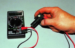
Checking the ABS sensor with a tester
A simple way to diagnose faults in the system is to check the ABS sensor with a tester. A tester (multimeter) is a device that allows you to measure current, network voltage and resistance. It allows you to find the location of a broken wire - one of the common causes of malfunctions in the anti-lock braking system.
Let's look at how to check the ABS sensor with a tester. In addition to the multimeter, we will need PINs (wires with special connectors) and instructions for repairing a specific car. The purpose of the test is to measure the resistance in the system circuit. To do this, you need to jack up the car or hang it on a lift and remove the wheel so that it does not interfere with access to the device being tested.
Further checking the ABS sensor with a multimeter involves the following steps:
When checking the ABS sensor with a tester, its readings should change along with the change in wheel speed.
- Remove the cover from the control unit and disconnect the controller connectors.
- Connect the PIN to the multimeter and the contact socket of the sensor being tested. Typically, the rear wheel sensor connectors are located under the car seats inside the passenger compartment.
- Set the tester to “Ohmmeter” mode and measure the circuit resistance at the device contacts. Please refer to the repair instructions for your machine for acceptable parameters. There you can also find out how to check which ABS sensor is not working. It is necessary to completely test the wiring of the anti-lock sensors for short circuits.
- Rotate the wheel manually back and forth while measuring the resistance. In this case, the multimeter readings should change along with the change in wheel speed.
- Switch the tester to another mode - “Voltmeter” mode. Measure the voltage at the sensor while also turning the wheel by hand. A voltage in the range of 0.25-1.3 Volts is optimal.

Removing the ABS sensor
By promptly identifying and eliminating the malfunction of your car's ABS brake system, you can avoid many troubles on the road and increase traffic safety.
We looked at the sequence of how to ring the ABS sensor with a tester. Then you need to correctly interpret the results. The tester readings must correspond to the data indicated in the repair instructions for your car. If the resistance in the circuit is below the minimum permissible factory value, this indicates a sensor malfunction. If the resistance fluctuates around zero, it is a sign of a short circuit. Jumping resistance is a sign of a violation of the integrity of the contacts inside the wiring. If there is no reading on the multimeter, this is a wire break.
Knowing how to check the ABS sensor for functionality, it is easy to then eliminate the malfunction itself. If the problem is the device itself, then it must be completely replaced with a new one. If irregularities are found inside the wiring, they can be easily eliminated using a simple soldering iron, carefully wrapping the sealed areas with insulating material. An experienced driver should know how to check the abs sensor with a tester, because these simple diagnostic procedures will allow you to timely identify faults in the brake system of your car and increase its level of safe operation.