Technical information about the starter and generator. About starter repair and generator repair. Automotive generator stator: description, principle of operation and diagram What does the generator stator consist of?
Read also
A modern car is literally packed with various electrical systems. The power supply for these systems is directly dependent on the generator, which consists of several components. The most important part of the generator is the generator stator. The operation of the generator and the power supply to the vehicle’s on-board system directly depend on its condition. When a generator breaks down, many rush to replace it with a new one, although it is easy to rebuild the generator and restore almost any part of it. For example, it is quite possible to rewind the generator stator with your own hands.
What elements does the stator of a synchronous generator consist of and the principle of operation?

Stator elements:
- Package of stator windings;
- Stator core or package;
- Wires for connection output.
The stator itself is made of three windings, three different current values are formed in them, this circuit is a three-phase output. The ends of each winding extend from the generator body (they are connected to it), the second end is connected to the rectifier. To concentrate and enhance the magnetic field in the generator, a core made of metal plates is used.
The stator winding of a synchronous generator is located in special slots, usually there are 36 such slots. In each slot, the winding is held by a wedge. This wedge is made of insulating materials.
Reasons for disruption of stable operation of the generator stator
Before checking, you need to find out exactly which generator is installed on your car. This can be found out from the manual, but the best way to find out the model and parameters of the generator is to look under the hood to find the manufacturer's tag. On it you will find all the necessary values. If differences in generator models are not taken into account, the test result will be inaccurate. Knowing the basics of electrics, it is not difficult to identify various problems in the operation of the generator, and other systems of the electrical system.
All stator failures can be divided into two groups:
- Broken winding wires;
- Wire short to ground.
If the vehicle is operated in conditions of high humidity or with sudden changes in temperature, the insulation may crack and delaminate. This can provoke an interturn short circuit and even failure of the entire generator, which will cause a sudden discharge of the battery, since the generator will not be able to fully charge it.
Checking the generator stator using a multimeter, how to check with a test light

The generator stator is checked for either an open circuit or a short circuit. To check the resistance, use a multimeter; in extreme cases, you can use a test light.
The multimeter should be switched to ohmmeter mode, after which its probes are connected to the terminals of the windings. If there is no break, the tester will show a resistance of 10 ohms. If there is a break, the resistance will show a value tending to infinity. With this result, three conclusions are checked. To obtain more accurate verification results, it is better to check the received data with your passport data. You should know that inexpensive Chinese multimeters are not able to accurately show the resistance being measured (accuracy is sometimes required to tenths of an ohm), so you should get a good branded device.
If it is not possible to get any multimeter, but you need to check, you can use a test light (control). It won't show the exact resistance, but it will help you find the gap. Using an insulated wire, a negative charge is supplied from the battery to the winding contact. A positive charge should be applied through the light bulb to another contact. If the light is on, then the gap has not been found and the device is functioning properly. This procedure is repeated for all outputs.
Diagnostics for short circuits is also carried out using a multimeter or a test light. The positive probe must be connected to any winding contact, and the negative probe to the stator. This should be repeated with each output. The turn-to-turn short circuit is determined using a test lamp in a similar way. Call all findings.
DIY generator repair

Stator repair usually means rewinding the generator stator. For this procedure you will need an impressive set of tools:
- Winding machine;
- Copper wire (about 8 coils may be required);
- Tamping;
- Drilling machine;
- Device for drying a varnished stator;
- Hammer, set of screwdrivers and keys.
Winding the stator of a car generator is the repair of the stator. First you need to remove the stator itself from the generator. The old winding is scorched, but before this, a diagram of the generator stator winding must be drawn up, identical to the old three-phase or single-phase winding. When scorched, the magnetic properties of the metal stator package do not deteriorate, so there is no need to worry. When the winding is completely burnt, the seat should be completely cleaned. Syntoflex insulating gaskets are cut and installed in the grooves.
The winding should be rewinded according to a pre-drawn pattern. The linear principle is used in a single-phase generator, and the three-phase stator winding involves a star or delta connection. When rewinding, the wire from the first groove should go directly to the fourth. First, half the turns are wound in one direction, then the second half in the opposite direction. The grooves are sealed with the protruding parts of the gaskets, after which the coils need to be tapped with a hammer. To avoid damaging the winding, you need to use a spacer.
Before checking the performance of the stator with currents, you should make sure that there is no short circuit. If there is a short circuit, it means the insulation was installed poorly. You should find the problem area and, using a gasket, eliminate the breakdown.
Before impregnation with varnish, you need to check the dimensions of the rewound unit; it should not protrude beyond the edges when assembling the generator. The contacts are connected with a thread that will not melt when dried and placed in a container with varnish. After impregnation of the stator, it is placed in an oven for drying, after allowing the element to flow around. If there is no suitable furnace, the stator can simply be suspended by installing a heating element underneath. When the varnish stops sticking, drying is complete. When using heating, drying usually takes about 2-3 hours.

When the generator operates unstable, for many the solution to the problem is to replace the entire unit. But if you know how to check all the elements of the generator, then even the stator winding procedure will be within your grasp.
If you have any questions, leave them in the comments below the article. We or our visitors will be happy to answer them
The generator is the main source of electricity for the machine. We'll tell you how it works, what its structure consists of.
How does he work?
When starting the engine, the main consumer of electricity is the starter; the current reaches hundreds of amperes, which causes a significant drop in battery voltage. In this mode, consumers are powered only by the battery, which is rapidly discharged. Immediately after starting the engine, the generator becomes the main source of power supply.The generator is a source of constant recharging of the battery while the engine is running. If it doesn't work, the battery will drain quickly. It provides the required current to charge the battery and operate electrical appliances. After recharging the battery, the generator reduces the charging current and operates normally.
When turning on powerful consumers (for example, a rear window defroster, headlights) and low engine speeds, the total current consumption may be greater than the generator is capable of delivering. In this case, the load will fall on the battery and it will begin to discharge.
Drive and mounting
The drive is carried out from the crankshaft pulley by a belt drive. The larger the diameter of the pulley on the crankshaft and the smaller the diameter of the pulley, the higher the speed of the generator, and accordingly, it is able to deliver more current to consumers.On modern machines, the drive is carried out by a poly-V-belt. Due to its greater flexibility, it allows the generator to be fitted with a small diameter pulley and hence high gear ratios. V-belt tension carried out by tension rollers with the generator stationary.
What is the device and what does it consist of?
Any generator contains a stator with a winding, sandwiched between two covers - the front, on the drive side, and the rear, on the slip ring side. The generators are bolted to the front of the engine on special brackets. The mounting feet and tension eye are located on the covers. The covers, cast from aluminum alloys, have ventilation windows through which air is blown by a fan. Generators of a traditional design are equipped with ventilation windows only in the end part, while those of a “compact” design are equipped with ventilation windows on the cylindrical part above the frontal sides of the stator winding.
 A brush assembly, which is combined with a voltage regulator, and a rectifier assembly are attached to the cover on the slip ring side. The covers are usually tightened together with three or four screws, and the stator is sandwiched between the covers, the seating surfaces of which cover the stator along the outer surface.
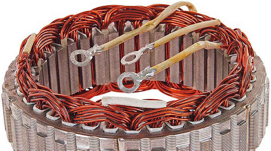
 Generator stator: 1 - core, 2 - winding, 3 - slot wedge, 4 - slot, 5 - terminal for connection to the rectifier
The stator is made from steel sheets with a thickness of 0.8...1 mm, but more often it is wound “on edge”. When making a stator package by winding, the stator yoke above the grooves usually has projections along which the position of the layers relative to each other is fixed during winding. These protrusions improve stator cooling due to a more developed outer surface.
The need to save metal led to the creation of a stator package design made up of individual horseshoe-shaped segments. The individual sheets of the stator package are fastened together into a monolithic structure by welding or rivets. Almost all mass-produced car generators have 36 slots in which the stator winding is located. The grooves are insulated with film insulation or sprayed with epoxy compound.
 Car generator rotor: a - assembled; b - disassembled pole system; 1,3 - pole halves; 2 - excitation winding; 4 - slip rings; 5 - shaft
A special feature of automobile generators is the type of rotor pole system. It contains two pole halves with protrusions - beak-shaped poles, six on each half. The pole halves are stamped and may have projections. If there are no protrusions when pressed onto the shaft, a bushing with an excitation winding wound on the frame is installed between the pole halves, and winding is carried out after installing the bushing inside the frame.
The rotor shafts are made of mild automatic steel. But when using a roller bearing, the rollers of which operate directly at the end of the shaft on the side of the slip rings, the shaft is made of alloy steel, and the shaft journal is hardened. At the threaded end of the shaft, a groove is cut for the key to attach the pulley.
Many modern designs do not have a key. In this case, the end part of the shaft has a recess or protrusion in the form of a hexagon. This allows you to keep the shaft from turning when tightening the pulley fastening nut, or when disassembling the generator, when it is necessary to remove the pulley and fan.
Brush unit- this is the structure in which the brushes are placed i.e. sliding contacts. There are two types of brushes used in automobile generators - copper-graphite and electrographite. The latter have an increased voltage drop in contact with the ring compared to copper-graphite ones. They provide significantly less wear on the slip rings. The brushes are pressed against the rings by spring force.
Rectifier units Two types are used. These are either heat sink plates into which the power rectifier diodes are pressed, or structures with highly developed fins and the diodes are soldered to the heat sinks. The diodes of the additional rectifier usually have a cylindrical or pea-shaped plastic housing or are made in the form of a separate sealed block, the inclusion of which is carried out in the circuit by busbars.
The most dangerous is the short circuit of the heat sink plates connected to the “ground” and the “+” terminal of the generator by metal objects accidentally falling between them or conductive bridges formed by contamination, because In this case, a short circuit occurs in the battery circuit and a fire is possible. To avoid this, the plates and other parts of the generator rectifier are partially or completely covered with an insulating layer. The heat sinks are combined into a monolithic design of the rectifier unit mainly by mounting plates made of insulating material, reinforced with connecting bars.
Generator bearing units These are typically deep groove ball bearings with one-time, lifetime grease and one or two-way seals built into the bearing. Roller bearings are used only on the slip ring side and quite rarely, mainly by American companies. The fit of ball bearings on the shaft on the side of the slip rings is usually tight, on the drive side - sliding, in the cover seat, on the contrary - on the side of the slip rings - sliding, on the drive side - tight.
The generator is cooled by one or two fans mounted on its shaft. In this case, in the traditional design of generators, air is sucked by a centrifugal fan into the cover from the side of the slip rings. For generators that have a brush assembly, a voltage regulator and a rectifier outside the internal cavity and are protected by a casing, air is sucked through the slots of this casing, directing the air to the hottest places - to the rectifier and voltage regulator. 
Cooling system: a - devices of conventional design; b - for increased temperature in the engine compartment; c - devices of compact design. Arrows show the direction of air flows
On cars with a dense engine compartment, generators with a special casing are used, through which cold outside air enters. For generators of a “compact” design, cooling air is taken in from both the rear and front covers.
What is a voltage regulator used for?
 The regulators maintain the generator voltage within certain limits for optimal operation of electrical appliances included in the vehicle's on-board network. The generators are equipped with semiconductor electronic voltage regulators built inside the housing. Their execution patterns and design may vary, but the principle of operation is the same.
 Voltage regulators have the property of thermal compensation - changing the voltage supplied to the battery, depending on the air temperature in the engine compartment for optimal battery charging. The lower the air temperature, the greater the voltage must be supplied to the battery and vice versa. The thermal compensation value reaches up to 0.01 V per 1°C. Some models of remote regulators have manual voltage level switches (winter/summer).
The device of a car generator
By design Generating sets can be divided into two groups:
- generators of traditional design with a fan at the drive pulley,
- generators of compact design with two fans in the internal cavity of the generator.
Typically, “compact” generators are equipped with a drive with an increased gear ratio through a poly-V-belt and therefore, according to the terminology adopted by some companies, are called high-speed generators.
According to the layout of the brush assembly, they are distinguished:
- generators in which the brush assembly is located in the internal cavity of the generator between the rotor pole system and the rear cover,
- generators, where slip rings and brushes are located outside the internal cavity (Fig. 1). In this case, the generator has a casing, under which there is a brush assembly, a rectifier and, as a rule, a voltage regulator.
Rice. 1. Alternator
The alternator contains stator With windings, sandwiched between two lids- front, on the drive side, and rear, on the side slip rings. The covers, cast from aluminum alloys, have ventilation windows through which air is blown by a fan through the generator.
Basic requirements for car generators
1. The generator must provide an uninterrupted supply of current and have sufficient power to:
- simultaneously supply electricity to working consumers and charge the battery;
- when all regular electricity consumers were turned on at low engine speeds, the battery was not severely discharged;
- the voltage in the on-board network was within specified limits throughout the entire range of electrical loads and rotor speeds.
2. The generator must have sufficient strength, long service life, small weight and dimensions, low noise level and radio interference.
Operating principle of the generator
The operation of the generator is based on the effect of electromagnetic induction. If a coil, for example, made of copper wire, is penetrated by a magnetic flux, then when it changes, an alternating electrical voltage appears at the coil terminals. Conversely, to generate a magnetic flux, it is enough to pass an electric current through the coil.
- Thus, to produce an alternating electric current, a coil is required through which a direct electric current flows, forming a magnetic flux, called the field winding, and a steel pole system, the purpose of which is to supply the magnetic flux to the coils, called the stator winding, in which an alternating voltage is induced.
These coils placed in the grooves of the steel structure, magnetic circuit(iron package) stator. The stator winding with its magnetic core forms generator stator (Fig. 3, item 1) - a stationary part in which an electric current is generated, and field winding With pole system and some other details ( shaft, slip rings) - rotor , rotating part.
The field winding can be powered from the generator itself. In this case, the generator operates at self-excitation. In this case, the residual magnetic flux in the generator, i.e., the flux that is formed by the steel parts of the magnetic circuit in the absence of current in the field winding, is small and ensures self-excitation of the generator only at too high rotation speeds. Therefore, such an external connection is introduced into the generator set circuit, where the field windings are not connected to the battery, usually through a generator set health lamp.
- The current flowing through this lamp into the excitation winding after turning on the ignition switch provides the initial excitation of the generator. The strength of this current should not be too high so as not to discharge the battery, but not too low, because in this case the generator is excited at too high speeds, so manufacturers stipulate the required power warning lamp- usually 2...3 W.
When the rotor rotates opposite the stator winding coils, the “north” and “south” poles of the rotor appear alternately, i.e., the direction of the magnetic flux passing through the coil changes, which causes the appearance of an alternating voltage in it. The frequency of this voltage f depends on the generator rotor speed n and the number of its pairs of poles R :
f=p*n/ 60
With rare exceptions, generators from foreign companies, as well as domestic ones, have six “south” and six “north” poles in the rotor magnetic system. In this case the frequency f 10 times less than the rotation speed of the generator rotor.
Since the generator rotor receives its rotation from the engine crankshaft, the frequency of the engine crankshaft can be measured by the frequency of the alternating voltage of the generator.
- To do this, a stator winding is made at the generator, to which the tachometer is connected. In this case, the voltage at the tachometer input has a pulsating character, since it turns out to be connected in parallel with the diode of the generator power rectifier.
Taking into account the gear ratio i belt drive from the engine to the generator signal frequency at the tachometer input f t related to engine speed n doors ratio:
f t =p*n dv (i)/ 60
Of course, if the drive belt slips, this ratio is slightly disrupted and therefore care must be taken to ensure that the belt is always sufficiently tensioned.
At R =6 , (in most cases) the above relation is simplified f t =n dv (i) /10 . The on-board network requires constant voltage to be supplied to it. Therefore, the stator winding powers the vehicle’s on-board network through rectifier , built into the generator.
Stator winding generators of foreign companies, as well as domestic ones - three-phase. It consists of three parts, called phase windings or simply phases, the voltage and currents in which are shifted relative to each other by a third of the period, i.e. by 120 0 (Fig. 2). The phases can be connected in star or delta. In this case, phase and linear voltages and currents are distinguished. Phase voltages U f act between the ends of the phase windings, and the currents I f flow in these windings, the linear voltages U l act between the wires connecting the stator winding to the rectifier. Linear currents flow in these wires J l . Naturally, the rectifier rectifies the values that are supplied to it, i.e. linear.

Rice. 2. Circuit diagram of an alternating current generator with a rectifier
The generator stator (Fig. 3) is made of steel sheets with a thickness of 0.8...1 mm, but is more often done by winding “on edge”. This design ensures less waste during processing and high manufacturability. When making a stator package by winding, the stator yoke above the grooves usually has projections along which the position of the layers relative to each other is fixed during winding. These protrusions improve stator cooling due to its more developed outer surface. The need to save metal led to the creation of a stator package design made up of individual horseshoe-shaped segments. The individual sheets of the stator package are fastened together into a monolithic structure by welding or rivets.

Rice. 3. Generator stator:
1 - core, 2 - winding, 3 - slot wedge, 4 - slot, 5 - terminal for connection to the rectifier
Almost all mass-produced car generators have 36 slots in which the stator winding is located. The grooves are insulated with film insulation or sprayed with epoxy compound.

Rice. 4. Generator stator winding diagram:
A - loop distributed, B - wave concentrated, C - wave distributed
------- 1st phase, - - - - - - 2nd phase, -..-..-..- 3rd phase
The slots contain the stator winding, made according to the circuits (Fig. 4) in the form of distributed loop (Fig. 4,A) or concentrated wave (Fig. 4,B), distributed wave (Fig. 4,C) windings. The loop winding is distinguished by the fact that its sections (or half-sections) are made in the form of coils with end-to-end connections on both sides of the stator package opposite each other. The wave winding really resembles a wave, since its frontal connections between the sides of the section (or half-section) are located alternately on one or the other side of the stator package. In a distributed winding, the section is divided into two half-sections emanating from the same slot, with one half-section emanating to the left and the other to the right. The distance between the sides of the section (or half-section) of each phase winding is 3 slot divisions, i.e. if one side of the section lies in the groove conventionally accepted as the first, then the second side fits into the fourth groove. The winding is secured in the groove with a groove wedge made of insulating material. It is mandatory to impregnate the stator with varnish after laying the winding.
A special feature of automobile generators is the type of rotor pole system (Fig. 5). It contains two pole halves with protrusions—beak-shaped poles, six on each half. The pole halves are made by stamping and may have protrusions - half-bushes. If there are no protrusions when pressed onto the shaft, a bushing with an excitation winding wound on the frame is installed between the pole halves, and winding is carried out after installing the bushing inside the frame.

Rice. 5. Car generator rotor: a - assembled; b - disassembled pole system; 1,3 - pole halves; 2 - excitation winding; 4 - slip rings; 5 - shaft
If the pole halves have half-bushings, then the excitation winding is pre-wound on the frame and installed when the pole halves are pressed on so that the half-bushings fit inside the frame. The end cheeks of the frame have retaining protrusions that fit into the interpolar spaces at the ends of the pole halves and prevent the frame from rotating on the bushing. Pressing the pole halves onto the shaft is accompanied by their caulking, which reduces the air gaps between the bushing and the pole halves or half-bushings, and has a positive effect on the output characteristics of the generator. When caulking, the metal flows into the grooves of the shaft, which makes it difficult to rewind the field winding if it burns out or breaks, since the rotor pole system becomes difficult to disassemble. The field winding assembled with the rotor is impregnated with varnish. The pole beaks at the edges are usually beveled on one or both sides to reduce magnetic noise from generators. In some designs, for the same purpose, an anti-noise non-magnetic ring is placed under the sharp cones of the beaks, located above the excitation winding. This ring prevents the beaks from oscillating when the magnetic flux changes and, therefore, emitting magnetic noise.
After assembly, the rotor is dynamically balanced, which is carried out by drilling out excess material at the pole halves. On the rotor shaft there are also slip rings, most often made of copper, crimped with plastic. The leads of the excitation winding are soldered or welded to the rings. Sometimes the rings are made of brass or stainless steel, which reduces wear and oxidation, especially when working in a humid environment. The diameter of the rings when the brush contact unit is located outside the internal cavity of the generator cannot exceed the internal diameter of the bearing installed in the cover from the side of the slip rings, since during assembly the bearing passes over the rings. The small diameter of the rings also helps reduce brush wear. It is precisely for the installation conditions that some companies use roller bearings as the rear rotor support, because ball ones of the same diameter have a shorter service life.
Rotor shafts are made, as a rule, of mild free-cut steel, however, when using a roller bearing, the rollers of which operate directly at the end of the shaft from the side of the slip rings, the shaft is made of alloy steel, and the shaft journal is cemented and hardened. At the threaded end of the shaft, a groove is cut for the key to attach the pulley. However, in many modern designs the key is missing. In this case, the end part of the shaft has a recess or protrusion in the form of a hexagon. This allows you to keep the shaft from turning when tightening the pulley fastening nut, or during disassembly, when it is necessary to remove the pulley and fan.
Brush unit- this is a plastic structure in which brushes are placed i.e. sliding contacts. There are two types of brushes used in automobile generators: copper-graphite and electrographite. The latter have an increased voltage drop in contact with the ring compared to copper-graphite ones, which adversely affects the output characteristics of the generator, but they provide significantly less wear on the slip rings. The brushes are pressed against the rings by spring force. Typically, brushes are installed along the radius of the slip rings, but there are also so-called reactive brush holders, where the axis of the brushes forms an angle with the radius of the ring at the point of contact of the brush. This reduces the friction of the brush in the guides of the brush holder and thereby ensures more reliable contact of the brush with the ring. Often the brush holder and voltage regulator form a non-separable unit.
Rectifier units are used in two types - either these are heat sink plates into which power rectifier diodes are pressed (or soldered) or on which the silicon junctions of these diodes are soldered and sealed, or these are structures with highly developed fins in which diodes, usually of the tablet type, are soldered to heat sinks. The diodes of the additional rectifier usually have a cylindrical or pea-shaped plastic housing or are made in the form of a separate sealed block, the inclusion of which is carried out in the circuit by busbars. The inclusion of rectifier units in the generator circuit is carried out by unsoldering or welding the phase terminals on special rectifier mounting pads or with screws. The most dangerous thing for the generator and especially for the wiring of the vehicle on-board network is the bridging of the heat sink plates connected to the “ground” and the “+” terminal of the generator by metal objects accidentally falling between them or conductive bridges formed by contamination, because In this case, a short circuit occurs in the battery circuit and a fire is possible. To avoid this, the plates and other parts of the rectifier of generators from some companies are partially or completely covered with an insulating layer. The heat sinks are combined into a monolithic design of the rectifier unit mainly by mounting plates made of insulating material, reinforced with connecting bars.
Generator bearing assemblies are usually deep groove ball bearings with a one-time grease for life and one or two-way seals built into the bearing. Roller bearings are used only on the slip ring side and quite rarely, mainly by American companies. The fit of ball bearings on the shaft on the side of the slip rings is usually tight, on the drive side - sliding, in the cover seat, on the contrary - on the side of the slip rings - sliding, on the drive side - tight. Since the outer race of the bearing on the side of the slip rings has the ability to rotate in the seat of the cover, the bearing and cover may soon fail, causing the rotor to touch the stator. To prevent the bearing from rotating, various devices are placed in the cover seat - rubber rings, plastic cups, corrugated steel springs, etc.
The design of voltage regulators is largely determined by their manufacturing technology. When making a circuit using discrete elements, the regulator usually has a printed circuit board on which these elements are located. At the same time, some elements, for example, tuning resistors, can be made using thick film technology. Hybrid technology assumes that resistors are made on a ceramic plate and connected to semiconductor elements - diodes, zener diodes, transistors, which in unpackaged or packaged form are soldered on a metal substrate. In a regulator made on a single crystal of silicon, the entire regulator circuitry is located in this crystal. Hybrid voltage regulators and single-chip voltage regulators cannot be disassembled or repaired.
The generator is cooled by one or two fans mounted on its shaft. In this case, in the traditional design of generators (Fig. 7, a), air is sucked into the cover by a centrifugal fan from the side of the slip rings. For generators that have a brush assembly, a voltage regulator and a rectifier outside the internal cavity and are protected by a casing, air is sucked through the slots of this casing, directing the air to the hottest places - to the rectifier and voltage regulator. On cars with a dense layout of the engine compartment, in which the air temperature is too high, generators are used with a special casing (Fig. 7, b) attached to the rear cover and equipped with a pipe with a hose through which cold and clean outside air enters the generator. Such designs are used, for example, on BMW cars. For generators of a “compact” design, cooling air is taken in from both the rear and front covers.

Rice. 7. Generator cooling system.
a - generators of conventional design; b - generators for elevated temperatures in the engine compartment; c - generators of compact design.
Arrows show the direction of air flows
High-power generators installed on special vehicles, trucks and buses have some differences. In particular, they contain two pole rotor systems mounted on one shaft and, consequently, two excitation windings, 72 slots on the stator, etc. However, there are no fundamental differences in the design of these generators from the designs considered.
Generator drive
The generators are driven from the crankshaft pulley by a belt drive. The larger the diameter of the pulley on the crankshaft and the smaller the diameter of the generator pulley (the ratio of the diameters is called the gear ratio), the higher the generator speed, and accordingly, it is able to deliver more current to consumers.
V-belt drive is not used for gear ratios greater than 1.7-3. First of all, this is due to the fact that with small pulley diameters, the V-belt wears out more.
On modern models, as a rule, the drive is carried out by a poly-V-belt. Due to its greater flexibility, it allows the installation of a small diameter pulley on the generator and, therefore, higher gear ratios, i.e. the use of high-speed generators. The tension of the poly V-belt is carried out, as a rule, by tension rollers when the generator is stationary.
Generator mounting
The generators are bolted to the front of the engine on special brackets. The mounting feet and tension eye of the generator are located on the covers. If fastening is carried out with two paws, then they are located on both covers; if there is only one paw, it is located on the front cover. In the hole of the rear paw (if there are two mounting paws) there is usually a spacer sleeve that eliminates the gap between the engine bracket and the paw seat.
Rectifier 1 contains six diodes VD1 - VD6, forming two arms: in one, the anodes of three diodes VD1 - VD3 are connected to the “+” terminal of the generator, and in the other, the cathodes of the diodes VD4 - VD6 are connected to the “-” terminal. In the single-wire circuit adopted on cars, the negative terminal is connected to ground. The leads of the phase windings of the generator stator are connected to the rectifier (the figure shows a star connection). The alternating voltages ip1 - ipz induced in the phase windings are shifted by 1/3 of the period, which is typical for a three-phase system.
AC rectifier
When the three-phase voltage changes over time, the rectifier diodes move from a closed state to an open state; as a result, the load current has only one direction - from the “+” terminal of the generator to the “-” terminal.
Rice. 8. Generator set diagram (a) and voltage diagrams (b):
1-phase bridge rectifier; 2-additional rectifier; 3-voltage regulator
As can be seen from Figure 8 b, at time 0, there is no voltage in winding L1; in winding L3 is positive, and in winding L2 is negative. The direction of the arrow towards the midpoint 0 of the stator winding is taken as positive voltage. The rectified current is supplied to consumers in the direction of the arrows through the diodes VD3 and VD4 that are in the open state.
At time t1 there is no voltage in winding L2, in winding L1 it is positive, and in winding L3 it is negative. The rectified current is supplied to consumers through diodes VD1 and VD5. In each arm of the rectifier, one diode is open for approximately 1/3 of the period.
The line voltage for a star connection is 1.73 times greater than for a delta connection. Therefore, when connecting in a triangle, there must be more turns in the stator winding than when connecting in a star. However, the phase current when connected in a delta is 1.73 times less than when connected in a star. Connecting the stator winding into a triangle for high-power generators allows it to be made from thinner wire.
The rectifiers of some generators have an additional arm connected to the midpoint 0 of the stator winding. This scheme allows you to increase the generator power by 15...20% due to the action of the third harmonic components of the phase voltage.
The rectified voltage Ud has a pulsating character. The GB battery serves as a kind of filter that smoothes the rectified voltage of the generator, while the battery current turns out to be pulsating.
In a valve generator, the rectifier diodes do not conduct current from the battery to the stator winding, and therefore there is no need for a reverse current relay. This significantly simplifies the generator set circuit. When parking the car for a long time, the battery may discharge to the excitation winding. Therefore, in some models of automobile generators, the excitation winding is connected to an additional rectifier 2. The additional rectifier is made of three diodes VD7-VD9, the anodes of which are connected to terminal D. In this case, only the voltage from the generator is supplied to the excitation winding through the additional rectifier 2 and rectifier arm 1 with diodes VD4-VD6.
The use of an additional rectifier also has a negative side associated with self-excitation of the generator. The generator can self-excite if there is a residual magnetic flux in it and a sufficiently low resistance of the excitation circuit. Therefore, to produce voltage in the operating range of rotation speeds of its rotor, the circuit uses a control lamp HL, which ensures reliable excitation of the generator.
A significant disadvantage of brush generators is the presence of a contact unit consisting of electric brushes and rings, through which current is supplied to the rotating excitation winding. This unit is subject to wear. Dust, dirt, fuel and oil getting on the contact unit quickly damage it.
Voltage regulators
The regulators maintain the generator voltage within certain limits for optimal operation of electrical appliances included in the vehicle's on-board network. All voltage regulators have measuring elements, which are voltage sensors, and actuators that regulate it.
In vibration controllers, the measuring and actuating element is an electromagnetic relay. For contact-transistor regulators, the electromagnetic relay is located in the measuring part, and the electronic elements are in the actuating part. These two types of regulators have now been completely replaced by electronic ones.
Semiconductor contactless electronic controllers are usually built into the generator and combined with the brush assembly. They change the excitation current by changing the time the rotor winding is switched on to the supply network. These regulators are not subject to misadjustment and do not require any maintenance other than monitoring the reliability of the contacts.
Voltage regulators have the property of thermal compensation - changing the voltage supplied to the battery, depending on the air temperature in the engine compartment for optimal battery charging. The lower the air temperature, the greater the voltage must be supplied to the battery and vice versa. The thermal compensation value reaches up to 0.01 V per 1°C. Some models of remote regulators (2702.3702, PP-132A, 1902.3702 and 131.3702) have stepped manual voltage level switches (winter/summer).
Operating principle of the voltage regulator
Currently, all generator sets are equipped with semiconductor electronic voltage regulators, usually built inside the generator. Their designs and design may be different, but the operating principle of all regulators is the same. The voltage of a generator without a regulator depends on the rotation speed of its rotor, the magnetic flux created by the field winding, and, consequently, on the current strength in this winding and the amount of current supplied by the generator to consumers. The higher the rotation speed and the excitation current, the greater the generator voltage; the greater the current of its load, the lower this voltage.
The function of the voltage regulator is to stabilize the voltage when the rotation speed and load changes by influencing the excitation current. Of course, you can change the current in the excitation circuit by introducing an additional resistor into this circuit, as was done in previous vibration voltage regulators, but this method is associated with a loss of power in this resistor and is not used in electronic regulators. Electronic regulators change the excitation current by turning on and off the excitation winding from the supply network, while changing the relative duration of the on-time of the excitation winding. If to stabilize the voltage it is necessary to reduce the excitation current, the switching time of the excitation winding is reduced; if it is necessary to increase it, it is increased.
It is convenient to demonstrate the operating principle of the electronic regulator using a fairly simple diagram of an EE 14V3 type regulator from Bosch, shown in Fig. 9:

Rice. 9. Diagram of the voltage regulator EE14V3 from BOSCH:
1 - generator, 2 - voltage regulator, SA - ignition switch, HL - warning lamp on the instrument panel
To understand the operation of the circuit, we should remember that, as shown above, the zener diode does not pass current through itself at voltages below the stabilization voltage. When the voltage reaches this value, the zener diode “breaks through” and current begins to flow through it. Thus, the zener diode in the regulator is the voltage standard with which the generator voltage is compared. In addition, it is known that transistors pass current between the collector and emitter, i.e. open if current flows in the base-emitter circuit, and do not allow this current to pass through, i.e. closed if the base current is interrupted. The voltage to the zener diode VD2 is supplied from the output of the generator "D+" through a voltage divider on resistors R1 (R3 and diode VD1, which performs temperature compensation. While the generator voltage is low and the voltage on the zener diode is lower than its stabilization voltage, the zener diode is closed through it, and, therefore, and no current flows in the base circuit of transistor VT1, transistor VT1 is also closed. In this case, the current through resistor R6 from the “D+” terminal enters the base circuit of transistor VT2, which opens, and current begins to flow through its emitter-collector junction in the base of transistor VT3 , which also opens.In this case, the excitation winding of the generator is connected to the power circuit through the emitter-collector junction VT3.
The connection of transistors VT2 and VT3, in which their collector terminals are combined, and the base circuit of one transistor is powered from the emitter of the other, is called a Darlington circuit. With this connection, both transistors can be considered as one composite transistor with a high gain. Typically, such a transistor is made on a single silicon crystal. If the voltage of the generator has increased, for example, due to an increase in the rotation speed of its rotor, then the voltage on the zener diode VD2 also increases, when this voltage reaches the value of the stabilization voltage, the zener diode VD2 “breaks through”, the current through it begins to flow into the base circuit of the transistor VT1, which The emitter-collector transition opens and short-circuits the base output of the composite transistor VT2, VT3 to ground. The composite transistor closes, breaking the power supply circuit of the field winding. The excitation current drops, the generator voltage decreases, the zener diode VT2 and transistor VT1 close, the composite transistor VT2,VT3 opens, the excitation winding is reconnected to the power circuit, the generator voltage increases and the process repeats. Thus, the generator voltage is regulated by the regulator discretely by changing the relative time of inclusion of the excitation winding in the power circuit. In this case, the current in the excitation winding changes as shown in Fig. 10. If the generator rotation speed has increased or its load has decreased, the winding turn-on time decreases; if the rotation speed decreases or the load increases, it increases. The regulator circuit (see Fig. 9) contains elements characteristic of the circuits of all voltage regulators used on cars. Diode VD3, when closing the composite transistor VT2, VT3, prevents dangerous voltage surges arising from an open circuit of the excitation winding with significant inductance. In this case, the field winding current can be closed through this diode and dangerous voltage surges do not occur. Therefore, the VD3 diode is called a quenching diode. Resistance R7 is the hard feedback resistance.

Rice. 10. Change in current strength in the field winding JB over time t during operation of the voltage regulator:
ton, toff - respectively, the time of turning on and off the excitation winding of the voltage regulator; n1 n2 - generator rotor speed, with n2 greater than n1; JB1 and JB2 - average current values in the field winding
When the composite transistor VT2, VT3 is opened, it is connected in parallel to the resistance R3 of the voltage divider, while the voltage on the zener diode VT2 decreases sharply, this speeds up the switching of the regulator circuit and increases the frequency of this switching, which has a beneficial effect on the quality of the generator set voltage. Capacitor C1 is a kind of filter that protects the regulator from the influence of voltage pulses at its input. In general, capacitors in the regulator circuit either prevent the circuit from going into oscillatory mode and the possibility of extraneous high-frequency interference influencing the operation of the regulator, or they speed up the switching of transistors. In the latter case, the capacitor, charging at one moment in time, is discharged onto the base circuit of the transistor at another moment, accelerating the switching of the transistor with the discharge current and, therefore, reducing its heating and energy loss in it.
From Fig. 9 the role of the HL lamp for monitoring the operating condition of the generator set (charge monitoring lamp on the car’s instrument panel) is clearly visible. When the car engine is not running, closing the contacts of the ignition switch SA allows current from the battery GA to flow through this lamp into the excitation winding of the generator. This ensures the initial excitation of the generator. At the same time, the lamp lights up, signaling that there is no break in the excitation winding circuit. After starting the engine, almost the same voltage appears at the generator terminals “D+” and “B+” and the lamp goes out. If the generator does not develop voltage while the car engine is running, the HL lamp continues to light in this mode, which is a signal of a generator failure or a broken drive belt. The introduction of resistor R into the generator set helps to expand the diagnostic capabilities of the HL lamp. If this resistor is present, in the event of an open circuit in the field winding while the car engine is running, the HL lamp lights up. Currently, more and more companies are switching to the production of generator sets without an additional excitation winding rectifier. In this case, the generator phase output is fed into the regulator. When the car engine is not running, there is no voltage at the generator phase output and the voltage regulator in this case goes into a mode that prevents the battery from discharging to the excitation winding. For example, when the ignition switch is turned on, the regulator circuit switches its output transistor into an oscillatory mode, in which the current in the field winding is small and amounts to fractions of an ampere. After starting the engine, the signal from the generator phase output switches the regulator circuit to normal operation. In this case, the regulator circuit also controls the lamp for monitoring the operating condition of the generator set.

Rice. 11. Temperature dependence of the voltage maintained by the Bosch EE14V3 regulator at a rotation speed of 6000 min-1 and a load current of 5A
For its reliable operation, the battery requires that as the temperature of the electrolyte decreases, the voltage supplied to the battery from the generator set increases slightly, and as the temperature rises, it decreases. To automate the process of changing the level of the maintained voltage, a sensor is used, placed in the battery electrolyte and included in the voltage regulator circuit. But this is only for advanced cars. In the simplest case, thermal compensation in the regulator is selected in such a way that, depending on the temperature of the cooling air entering the generator, the generator set voltage changes within specified limits. Figure 11 shows the temperature dependence of the voltage supported by the Bosch EE14V3 regulator in one of the operating modes. The graph also shows the tolerance range for this voltage. The falling nature of the dependence ensures a good charge of the battery at negative temperatures and prevents increased boiling of its electrolyte at high temperatures. For the same reason, on cars designed specifically for use in the tropics, voltage regulators are installed with a deliberately lower setting voltage than for temperate and cold climates.
Operation of the generator set in different modes
When starting the engine, the main consumer of electricity is the starter; the current reaches hundreds of amperes, which causes a significant voltage drop at the battery terminals. In this mode, electricity consumers are powered only by the battery, which is intensively discharged. Immediately after starting the engine, the generator becomes the main source of power supply. It provides the required current to charge the battery and operate electrical appliances. After recharging the battery, the difference between its voltage and the generator becomes small, which leads to a decrease in the charging current. The power source is still the generator, and the battery smoothes out the generator voltage ripples.
When powerful consumers of electricity are turned on (for example, a rear window defroster, headlights, heater fan, etc.) and a low rotor speed (low engine speed), the total current consumption may be greater than the generator is capable of delivering. In this case, the load will fall on the battery and it will begin to discharge, which can be monitored by readings from an additional voltage indicator or voltmeter.
When installing the battery into the vehicle, make sure the connection polarity is correct. An error will lead to immediate failure of the generator rectifier and a fire may occur. The same consequences are possible when starting the engine from an external current source (lighting up) if the connection polarity is incorrect.
When operating a vehicle you must:
- monitor the condition of the electrical wiring, especially the cleanliness and reliability of the connection of the contacts of the wires suitable for the generator and voltage regulator. If the contacts are poor, the on-board voltage may exceed permissible limits;
- disconnect all wires from the generator and from the battery when electrically welding car body parts;
- Make sure the alternator belt is properly tensioned. A belt that is loosely tensioned does not ensure efficient operation of the generator; a belt that is tensioned too tightly leads to the destruction of its bearings;
- Immediately find out the reason for the generator warning lamp to come on.
The following actions are unacceptable:
- leave the car with the battery connected if you suspect a malfunction of the generator rectifier. This can lead to a complete discharge of the battery and even a fire in the electrical wiring;
- check the functionality of the generator by shorting its terminals to ground and to each other;
- check the serviceability of the generator by disconnecting the battery while the engine is running due to the possibility of failure of the voltage regulator, electronic elements of injection systems, ignition, on-board computer, etc.;
- do not allow electrolyte, antifreeze, etc. to come into contact with the generator.
Checking the field winding for interturn short circuit
The interturn short circuit causes an increase in the excitation current. Due to overheating of the winding, the insulation is destroyed and even more turns are shorted together. An increase in excitation current may lead to failure of the voltage regulator. This malfunction is determined by comparing the measured field winding resistance with the specifications. If the winding resistance has decreased, then it is rewound or replaced.
The interturn short circuit in the excitation winding coil is determined by measuring the resistance of the excitation coil using an ohmmeter available at stands E211, 532-2M, 532-M, etc., a separate portable ohmmeter (see Fig. 14, c), or according to the readings of an ammeter and voltmeter when the winding is powered from a battery (see Fig. 14, d). The fuse protects the ammeter and battery in the event of an accidental short circuit. Probes are connected to the rotor slip rings and by dividing the measured voltage by the current, the resistance is determined and compared with the technical specifications (see Table 2).
Rice. 14. Checking the field winding:
a-on a cliff; b-to short circuit with shaft and pole; c - with an ohmmeter for open circuit and interturn short circuit; g — — connection of instruments for determining resistance.
Checking the stator winding for a break. Checking the stator winding for a break is carried out using a test lamp or an ohmmeter. The lamp and power source are alternately connected to the ends of the two phases according to the diagram in Fig. 15, a. If there is a break in one of the coils, the lamp will not light. An ohmmeter connected to this phase will show “infinity.” When connected to the other two phases, it will show the resistance of those two phases.
Interturn short circuit in the generator winding. How to detect. Advice from an auto electrician.
Interturn short circuit in the stator winding of the generator.
If the channel brings you real benefits, then support the project! The amount doesn't matter! CARD (SBERBANK)…
Checking the stator winding for a short circuit with the core. If such a malfunction occurs, the power of the generator is significantly reduced or the generator does not work, and its heating increases. The battery is not charging. The test is carried out with a 220 V test lamp. The lamp is connected to the core and any winding terminal according to the diagram in Fig. 15, b. If there is a short circuit, the lamp will light up.
 Checking the stator winding for interturn short circuit. Interturn short circuit in the stator winding coils is determined by measuring the resistance of the phase coils with a separate ohmmeter (see Fig. 15, c), on stands E211, 532-2M, 532-M and others, or according to the diagram shown on rice. 15, g. If the resistance of two windings (measured or calculated) is less than that indicated in the table. 2, then the stator winding has an interturn short circuit. This fault can be detected using the stator winding zero point. To do this, it is necessary to measure or calculate the resistance of each phase separately and, comparing the resistance
Rice. 15. Checking the stator winding:
a - on a cliff; b - for short circuit with the core; c - for interturn short circuit and open circuit
ohmmeter; d - connection of instruments to determine the resistance of the stator winding
all three phases, determine which of them has an interturn short circuit. A phase winding that has an interturn short circuit will have less resistance than others. The defective winding is replaced.
The serviceability of the stator windings can be checked on test benches for phase symmetry. During this test, the alternating voltage is measured between the phases of the stator winding up to the rectifier unit at the same (constant) generator rotor speed. If the voltage induced (induced) in the stator windings is not the same, then this indicates a malfunction of the stator winding.
To measure the voltage of two phases, the wires of the stand voltmeter through the windows of the generator cover alternately touch two radiators of the rectifier block (for generators with rectifier blocks of the VBG type) or the heads of the screws connecting the stator winding and the rectifier block (for generators with rectifier blocks of the BPV type).
Not a single modern car can “live” without electrical equipment. And the main component of all electrical equipment is the most important source - the generator. In turn, it contains an equally important component that contributes to the generation of electricity while the car is moving. We are talking about the generator stator.
What is it for, what is its purpose and what malfunctions can there be? We'll talk about this and something else in this article.
Car electrical equipment
All electrical equipment of any car is represented by the following components:
- Current sources:
- accumulator battery;
- generator.
- Current consumers:
- basic;
- long-term;
- short-term.
The task of the battery is to provide consumers with current while the engine is “resting”, during its startup or operation at low speeds. While the generator is, in fact, the main supplier of electricity. It not only powers all consumers, but also charges the battery.
Its capacity, combined with the power of the generator, must meet the needs of all consumers, regardless of the engine operating mode. In other words, it must be constantly maintained. This is important to know, as it will allow you to understand how the generator stator works.
TO main consumers It is customary to refer to the fuel system, including injection, ignition, control, and automatic transmission. Some cars have electric power steering. That is, everything that constantly uses current, from starting the engine to stopping it completely.
Long-term consumers are systems that are not used too often. And this is lighting, security (passive, active), heating and air conditioning devices. Most cars are equipped with anti-theft systems, multimedia equipment and navigation.
Concerning short-term consumers, then this is the cigarette lighter, starting system, glow plugs, signal, as well as comfort systems.
Design features
The generator is present in every car and consists of the following components:
- stator;
- rotor;
- brush assembly;
- rectifier block.
Both the generator stator and everything else are assembled into a relatively compact module, which is installed in close proximity to the engine and operates from the rotation of the crankshaft, for which a belt drive is used.
Functional purpose
The stator is a stationary element of the entire structure and is fixed to the generator housing. In turn, it contains a working winding, and during operation of the generator it is in it that electricity is awakened. However, such current is variable in nature, and all consumers need direct voltage. The transformation (straightening, so to speak) occurs precisely thanks to the rectifier unit.

Among the main tasks of the stator is the load-bearing function for holding the working winding. It also ensures the correct distribution of magnetic field lines. During operation of the generator, the working winding can become very hot. And here another equally important function comes into force - removing excess heat from the winding.
As a rule, all modern cars use the same type of stator design.
Stator device
The design of the generator stator is formed by the following components:
- ring core;
- working winding;
- winding insulation.
Let's take a closer look at these components.
Core. These are ring plates, on the inside of which there are grooves for the location of the winding. The connection of the plates is very tight, and together they form a so-called package. The rigidity of a monolithic structure is imparted by welding or riveting.
For the manufacture of plates, special grades of iron or ferroalloys are used, which are distinguished by the presence of a certain magnetic permeability. Their thickness ranges from 0.8 to 1 mm. For better removal of thermal energy, ribs are provided, which are located on the outside of the stator.

Winding. As a rule, it is used in cars where there are three windings, one for each phase. For their manufacture, copper wire is used, which is coated with insulating material. Its diameter is 0.9-2 mm, and it is placed in the grooves of the core in a special way.
Each of the stator windings of a VAZ generator (or any other brand) has a terminal for removing current. As a rule, the number of these terminals does not exceed 3 or 4. However, there are stators that have 6 terminals. Moreover, each winding has its own number of pins for a specific type of connection.
Insulation. Insulation is placed in each core groove to protect the wire from damage. In some cases, special insulating wedges can be placed in the grooves for more reliable fixation of the winding.

The stator is impregnated with epoxy resins or varnishes. This is done in order to ensure the integrity and strength of the entire monolithic structure, which eliminates the shift of the winding turns. Electrical insulation characteristics are also improved.
How does a stator work?
The principle of operation of the stator, and therefore the entire unit (generator), of any modern car is based on one phenomenon that is familiar to each of us since physics lessons. They often mentioned such concepts as generator, rotor, stator. We are talking about electromagnetic induction. Its essence is as follows: when any conductor moves in the area of action of a magnetic field, a current is generated in it.

Or this conductor (stator) may be in an alternating magnetic field (rotor). This is the principle used in car generators. When the engine starts, the generator rotor begins to rotate. At the same time, the voltage from the battery reaches the working winding. And since the rotor is a multi-pole steel core, when voltage is applied to the winding it becomes an electromagnet.
As a result of rotor rotation, an alternating magnetic field is created, the lines of force of which intersect the stator. And here the “conductor” core comes into play. It begins to distribute the magnetic field in a special way, and its lines of force intersect the turns of the working winding. And thanks to electromagnetic induction, a current is generated that is removed by the stator terminals. Next, the resulting alternating voltage is supplied to the rectifier unit.
As soon as you increase the number of crankshaft revolutions, the current flows partially from the generator stator winding to the rotor winding. Thus, the generator switches to self-excitation mode, and it no longer needs a third-party voltage source.
Main stator faults
As a rule, the main stator failures are:
- "Breakage" of the working winding.
- There is a short circuit.
A characteristic sign by which one can judge that the stator is not working properly is the loss of charging current. This may be indicated by a low battery indicator that does not go out after starting the engine. The voltmeter needle will be closer to the red zone.

When measuring the voltage at the battery while the engine is running, the voltage will be less than the required value. For the battery itself this is at least 13.6 V, and for the generator - 37.3701 V. Sometimes, in the event of a short circuit on the windings, you can hear a characteristic howl emitted by the generator.
During vehicle operation, the alternator may become hot and may be subject to electrical loads. In addition, he has to work in negative conditions of external factors. Over time, this inevitably leads to deterioration of the winding insulation, which causes electrical breakdowns. Then the problem can be solved by repair (rewinding the generator stator) or completely replacing it.
Checking the health of the stator
Some beginners are increasingly concerned with the question of how to check whether all parts of the generator are in working order. To do this, you will need special small equipment in the form of a multimeter (popularly just a tseshka). You can use an autotester or another device that has an ohmmeter mode. As a last resort, a 12 V light bulb with wires soldered to it will do.
First you need to remove the generator from the car and disassemble it. Depending on the brand of car, there may be difficulties, since on some Lexus brand models the power source is located in a hard-to-reach place. Having reached the stator and removed it, it is necessary to clean it from dirt. Then you can proceed to the verification itself.
Checking for open circuit
How to check the generator stator for a break? To begin with, you should switch the measuring device to ohmmeter mode, after which we bring the probes to the winding terminals. If there is no break, the multimeter will show values below 10 ohms. Otherwise, the readings will tend to infinity. Thus, no current passes through the winding, which indicates the presence of a break. So you need to check all the conclusions.

If using a light bulb, we check in the following sequence. First, we connect the negative wire to one of the winding terminals with a wire (preferably insulated). We supply the plus batteries to the other terminal through the lamp. Its light will indicate complete order, but if the lamp does not light up, it means there will be a break. This must be done with every conclusion.
Check for short circuit
Now it’s worth checking the stator for a short circuit. In ohmmeter mode, we bring the negative probe to the stator housing, and the positive probe to any of the terminals of the working winding. Normally, the readings should tend to infinity. Repeat the procedure for each of the terminals.
With a light bulb, checking the generator stator occurs as follows:
- We connect the negative side of the battery with a wire to the stator housing.
- The positive terminal is fed to any output through the light bulb.
A short circuit will be indicated by a lit light. If it doesn’t catch fire, then everything is in perfect order.
Small note
The listed malfunctions are typical not only for the generator stator; the voltage regulator, the diode bridge, and the generator rotor may also come into question. It is worth noting that poor performance of the stator is much less common than with the listed components of any generator.

Therefore, before working on the stator, it is necessary to check the voltage regulator and diode bridge. And if they turn out to be in perfect order, then the last thing to do is winding.
For reliable operation of all electrical equipment of the car, regular maintenance should be carried out and, if necessary, the generator stator should be replaced immediately. The price in the end will not seem as high as replacing the entire generator.
As for the cost, prices for new parts start at 1,500 rubles with three terminals. Products with six contacts will cost more - 6-7 thousand rubles, although there are cheaper options. However, it all depends on the make of the car.