Diagnostics and principle of operation of the abs sensor. How to check the knock sensor How to measure the resistance of the abs sensor
Sometimes while driving, a car's gasoline engine begins to make a suspicious metallic knock. Drivers call it "tapping fingers." This sound is a sign of detonation, an extremely undesirable phenomenon that can lead to engine failure and the need for costly repairs. To prevent this from happening, a knock sensor is installed on the cylinder block. If it breaks, you can check it with your own hands.
How the sensor works
The phenomenon of detonation occurs for various reasons. This includes the use of low octane gasoline, a high compression ratio, and many other factors. What matters is driving in certain gears, the degree of soot, and the presence of certain components in the working mixture.
The knock sensor is an accelerometer that analyzes the mechanical vibrations of the cylinder block and converts them into electrical impulses. The principle of operation is simple: the device constantly sends signals to the electronic control unit of the power unit. That, in turn, changes the composition of the mixture and the ignition timing depending on these signals. The result is proper use of resources and engine operation at optimal power.
How to understand that it is out of order
The product is installed in cars with an electronic control circuit. Diagnosing faults in such machines is simple - if everything works correctly, the sensors on the dashboard remain inactive. The main sign of a malfunctioning knock sensor is the appearance of the inscription “Check engine” (CHECK). It can burn constantly, or it can appear and disappear.
If the sensor breaks down, acceleration performance deteriorates. The car starts, but works worse - it accelerates poorly, vibration occurs at rpm below 1000, power drops and fuel consumption increases, and the amount of smoke from the exhaust increases.
Why is this happening? Sensor malfunctions are related to automotive electronics. The following reasons are possible:
- the signal wire is broken;
- a short to ground has occurred;
- there was a short circuit in the on-board network of any wire of the device;
- the shielding braid is damaged;
- the power unit control unit has failed;
- something is damaged inside the sensor itself.
Checking the knock sensor
Since breakdowns occur for various reasons, you will have to check several elements of the system. Inspect the condition of the sensor wires, check the harness sockets and sensor plugs. Evaluate the reliability of their connections. If everything is in order here, check the contacts of the socket. Found damaged components? Replace them. It is also recommended to examine the condition of the tourniquet. Turn off the ignition, disconnect the harness from the sensor and check it with an ohmmeter. This way you will know if the chain is intact.
Sometimes the problem lies in the condition of the shielding braid. In this case, we proceed as follows.
- We look to see if the harness sockets and plugs are securely connected;
- We study each of their components;
- We check whether the shielding braid is intact.
If the cause of the malfunction is a short to ground, you must proceed using another method:
- We disconnect the entire block from the harness, along with the knock sensor;
- We check the integrity of the chain, look for heavily worn places;
- Turn off the ignition and, using an ohmmeter, examine the place where the engine mass is connected to the harness circuit.
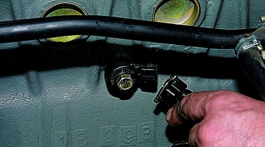
 We find and dismantle the sensor
 Checking parts for one or two wires using a multimeter
The first thing to do is to find out what resistance is typical for a properly functioning sensor in a particular car. The figure varies greatly among different manufacturers.
This is interesting: resistance indicators can be the most unexpected. So, in VAZ cars with injection engines it is almost impossible to measure it because the indicators are too high. In Nissan and Subaru the figures are about 550 kOhm, in Hyundai - about 5 MOhm (megaohm).
To carry out the tests, you will need a multimeter, and a fairly sensitive one, as well as a socket wrench of size “13” or “22”, depending on the size of the installed sensor. To test resistance, switch the tool to kOhm resistance mode and attach it to the probe. If a two-pin sensor is installed in the car, the connection is made to the terminals; in the case of a single-contact model - to the contact and the body.
Now lightly tap the sensor with a metal object - a screwdriver or bolt. Pay attention to the multimeter readings. If there are deviations from the values specified in the instructions, a breakdown has occurred.
It is recommended to check whether there is voltage at the electrical ends. Disconnect the electrical connector of the sensor and remove it from the engine. Switch the multimeter to millivolts and connect the “+” probe to the signal pin. The “-” probe must be connected to the sensor ground. This part is easy to recognize - it is a hole through which the mounting bolt to the motor passes.
Hold the sensor in your palm and lightly tap it on a surface. The result should be a voltage - typically between 30 and 40 mV. If no potential difference occurs, then the sensor has failed.
There are no particular differences in testing for broadband and resonant sensors.
 We connect the sensor to the multimeter and knock it on a hard object
 Diagnostics with a dial tester or voltmeter
- In addition to a multimeter, you can use a pointer tester - the actions are similar to working with a multimeter.
- There is another way. With the engine idling, connect an AC voltmeter to the sensor. Tap the knock control component with a hard, non-metallic object. If the voltmeter shows that the amplitude of the signal from the device is below 0.1 V, the device is faulty.
Video on how to check
Repair or replacement?
You decide. The cost of the product depends on the car model and the manufacturer of the component - for a replacement you will need to pay an amount approximately equal to its price. You can change the device yourself; for this you will need a room with a pit. Self-repair is also possible: if you are well versed in cars, it will take no more than an hour.
The coolant temperature sensor (CTS) is the most important element of the car, on which timely notification of the driver about engine overheating depends. As you can guess from its name, its purpose is to measure the temperature of the coolant. It is part of the engine control system, and various engine operating parameters are regulated from its readings: ignition timing, percentage of fuel in the working mixture, crankshaft speed and many others.
The coolant temperature sensor design is quite banal. It is a thermistor located in the housing. A thermistor is a resistor with the distinctive feature that its resistance decreases with increasing temperature.
A failure of the coolant temperature sensor can lead to other problems. It is important to monitor its condition, and if symptoms of a malfunction occur, check the coolant temperature sensor and, if necessary, replace it with a new one.
What indicates a faulty coolant temperature sensor

The easiest way to diagnose a problem with the coolant temperature sensor is by its appearance. In most cases, it fails due to damage, which can be mechanical or corrosive. If the sensor housing is cracked, you can forget about its stable operation. In this case, the thermistor itself located in the housing may also fail, and a malfunction of the coolant temperature sensor in this case will be indicated by:
- Warning lamp signaling the driver about engine overheating;
- Noticeable increase in gasoline consumption;
- Problems with the engine: difficulty starting, spontaneous stopping, unstable idle speed and other malfunctions;
- Errors on the dashboard determined by the electronic control unit (their numbers vary depending on the model and manufacturer of the car).
If there are symptoms indicating a malfunction of the coolant temperature sensor, you can immediately replace it. The price of such a device is low, especially for common car models. If desired, you can diagnose it to make sure that the sensor is the source of the problems.
Where is the coolant temperature sensor located?
 DTOZH is a small plastic device with a metal thread. With its help, it is attached to the exhaust pipe of the cylinder head, screwing into it. The sensor must be positioned so as to have direct contact with the coolant, from which it can be concluded that its readings are inaccurate when its level is low.
Important: Some car models may have two coolant temperature sensors. In this case, one of them records the temperature at the engine outlet, and the second at the radiator outlet.

Before you start checking the sensor itself, you need to make sure that there is no fault in the car's wiring. For the DTOZH to work correctly, a voltage of 5 Volts must be constantly supplied to it. This is quite simple to check; you need to disconnect the wires from the coolant temperature sensor and check the voltage output from them with the engine running using a voltmeter (multimeter). If no problems are found and 5 Volts are supplied to the sensor, you can begin diagnosing the thermistor itself.
To check the coolant temperature sensor for correct resistance determination, you will need: a multimeter, a thermometer, an electric kettle (or other device capable of constantly heating water), and a key for removing the sensor.
When the tools are prepared, the first thing you need to do is remove the sensor from the car. Next, you can proceed in two ways.
Method 1: Checking the DTOZH in an electric kettle
The first way to diagnose a sensor is to test it using an electric kettle. To do this you need:
- Place a thermometer (preferably an electronic one, since you will need to measure high temperatures) in a kettle with cool water;
- Next, connect a multimeter to the sensor (in the position for measuring resistance);
- Place the sensor in the kettle;
- Measure the sensor reading and write it down;
- Turn on the kettle and record the sensor resistance readings when the key heating points are reached - +10, +15, +20 degrees Celsius and so on;
- Compare your results with the table below.

If the values obtained differ greatly from the ideal values, then the coolant temperature sensor is faulty and will need to be replaced.
Method 2: Checking the DTOZH without a thermometer
 A less accurate but easier way to check the sensor is without using a thermometer. Its essence lies in the fact that when water is heated, it reaches 100 degrees Celsius, and its temperature cannot rise higher. Accordingly, this point can be taken as a control value and the resistance of the sensor can be measured at a given temperature.
The use of an ABS sensor is associated with its induction properties (the sensor itself is an induction coil and a toothed ring). Due to these properties, the sensor can read pulses, transmitting them to the control unit. The control unit is responsible for the proper functioning of the hydraulics, and, receiving information from the sensor, regulates the oil pressure in the brake system. The ABS sensor, like other sensors in the car, may one day fail and the ABS sensor will need to be checked - this is a normal procedure that should be performed periodically.
The most common problem that occurs with the ABS sensor is a disruption in the circuit connecting the sensor to the control unit, as well as a breakdown of the sensor - these problems begin to distort the information received and transmit false data to the control unit.
A violation of the anti-lock system is detected while driving, as well as by the ABS light on the dashboard. The exact cause of the breakdown can only be determined after a thorough diagnosis.
The driver's first actions when the ABS light is on
Of course, a lit indicator light forces you to check the ABS sensor first. This can be done without going to a car service center. At the same time, for a correct check, the car owner will need a multimeter, an operating manual for the car, and wiring with PIN connectors. Yes, you can’t do without an extra pair of hands either.
How to check resistance
The multimeter operates in ohmmeter mode
- Using a jack or lift, raise the car;
- We dismantle the wheel (if, in your car model, it is an obstacle to the sensor);
- We tighten the screw that secures the sensor (it is located behind the hub);
- We dismantle the casing protecting the ABS control unit, and then disconnect all connectors going to the controllers;
- We include wiring with PIN connectors in the circuit, connecting them to the multimeter and to the sensor;
- We measure the resistance, checking the standard data from the instruction manual;
- We check the wiring to eliminate the possibility of a short circuit.
Using the help of a partner, you need to manually rotate the wheel several times, recording the resistance indicators. When the rotation speed changes, the instrument readings should also change.
For a working ABS sensor, the multimeter will show the following indicators:
- For the sensor-leg circuit: 5-26 Ohm;
- For the sensor-ground circuit (circuit insulation check): at least 20,000 Ohms.
How to check voltage
The multimeter operates in voltmeter mode
- We lift the car on a jack, hanging its wheels;
- We connect the PIN connectors of the pre-prepared wiring to the contact of the multimeter;
- We begin to rotate the wheel, trying to maintain the rotation speed at 1 revolution per second;
During normal operation of the sensor, the voltmeter readings will range from 0.25 Volts to 1.2 Volts. Please note that increasing the wheel speed will lead to an increase in the readings of the device.
Additional diagnostic options
You can also check the ABS sensor using an oscilloscope, which measures the amplitude and resistance values. However, an oscilloscope is very expensive, and it is much more difficult to use than a multimeter.
Another way to understand what exactly is broken when the ABS light is on is to decipher the information that the anti-lock braking system on new cars represents. As soon as such a system is activated, it displays coded errors on the car’s on-board computer screen. It is not difficult to decipher such errors; just study the machine’s operating manual, or find information on the error code on the Internet.
Attention! When checking the ABS sensor and connecting the multimeter wires to it, you need to observe the polarity. This is written in detail in the vehicle's Operation Manual: in particular, the color markers of the wires are described there and all connecting connectors are indicated.
Only after thoroughly checking the operation of the ABS sensor can you begin to repair or replace it. Repair means soldering damaged ABS sensor wiring and protecting the wire connections with a layer of electrical tape.
Video: Checking the ABS sensor
If the video does not show, refresh the page or
The crankshaft position sensor is an important element of the car, synchronizing the operation of the engine control unit. If it is damaged, synchronization will be disrupted, which will lead to breakdowns. However, the malfunction of this element is difficult to identify on your own, because this requires knowledge and appropriate tools.
Although often the breakdown of this element makes it impossible to start the engine, this is not always the case. If the crankshaft sensor is faulty, it can significantly reduce the efficiency of the vehicle, disrupt the timing of the fuel supply, cause spontaneous changes in speed, and much more.
Signs of sensor malfunction
A breakdown of the crankshaft sensor can be confused with problems with other vehicle mechanisms, including the fuel injection system or the unit that controls engine operation. Therefore, it is necessary to distinguish the characteristic features of this case, focusing on the “symptoms” of the car. Common symptoms of crankshaft sensor problems include:
- spontaneous change in speed dynamics;
- significant reduction in crankshaft characteristics;
- lack of stability in idle speed;
- problems starting the engine;
- detonation is possible in the engine under load.
These are just the main nuances that indicate a breakdown of the crankshaft sensor. They can be confused with problems with the generator or timing pulley. There are many signs of sensor failure, but most of them are individual and appear only in special cases.
However, nothing can be achieved by guessing; with such signs, it is worth taking the car to a service center or checking the condition of the crankshaft sensor yourself. Although it is quite difficult to reach, using the instructions will allow you to quickly get to it and check its functionality. The test is quite simple and gives an accurate result that will indicate the health of the device.
Preparing the sensor before testing

There are several methods used to test this device. The simplest of them is to use a tester or multimeter, which will allow you to determine the condition of the crankshaft sensor based on its characteristics. However, it is also possible to use an oscilloscope, which is more often found in service workshops.
Before testing, you must remove the device from the vehicle. This is done in the following order:
- The ignition is turned off.
- The sensor connector is disconnected.
- The securing bolt is removed.
- The device itself is removed.
The procedure for removing the mounts may vary depending on the vehicle and the mounting method.
Advice! To remove the bolt, use a 10mm wrench. The place is difficult to access, so you can’t get there with bulky tools.
During the removal process, it is worth carrying out an external inspection of the device. If the breakdown is significant, then it can be noticed without any diagnostics. If the crankshaft sensor has severe external damage or cracks, then it should be replaced without additional checks.
Advice! When removing the device, it is better to make marks that determine its original position. This will simplify its further installation after testing.
After removing the sensor, you must thoroughly clean it of all contaminants. Before further testing, the contacts of the device must be clean, which will reliably determine its functionality.
Checking the sensor with a multimeter
For the first diagnostic method, you need to use a multimeter or tester. It is enough just to measure the resistance of the device winding by connecting it to the measuring equipment. If the winding has been damaged, this will affect the resistance readings.

Since a damaged coil changes the resistance of the crankshaft sensor, this test will determine its condition. You need to set the required range and connect the probes to the device outputs.
After checking, it is worth checking the received readings with the original ones. The average resistance of a working crankshaft sensor varies between 550-750 Ohms, but you can find the exact value in the technical instructions for the car. There probably is an accurate resistance indicator there.
Important! This test is unreliable and cannot guarantee an accurate test result. However, it is the simplest to perform, so if you have a multimeter, this will allow you to identify significant problems in the device.
There is also a second method for determining the performance of the crankshaft sensor. It is much more difficult, and to carry it out you need to take several devices, including:
- inductance meter;
- voltmeter;
- megohmmeter;
- network transformer.
The last two devices are replaced by a multimeter if it supports these functions.
The following measurements must be taken:
- Measuring winding resistance using an ohmmeter.
- Measuring winding inductance using an inductance meter.
- Determination of insulation resistance using a megohmmeter. Having applied a voltage of 500V, it is necessary to determine the resistance value.
Based on the data obtained, the condition of the crankshaft sensor is determined. Each indicator has a certain norm that you should focus on. The inductance of the winding varies between 200-400 mH; going beyond this range indicates a malfunction of the device. The winding resistance standard was previously mentioned and is 550-750 Ohms.
When measuring insulation resistance, the resulting value should not exceed 20 MΩ.
This data will allow you to determine the functionality of the device or the presence of breakdowns, which will lead to its further replacement. However, there are more accurate diagnostic methods, among which the main one is checking with an oscilloscope. It is used at professional service stations and provides a complete diagnosis of this element.
Important! After diagnosing the device, it is worth checking the synchronization disk for magnetization. If it has received an extra charge, then it is worth demagnetizing it using a transformer.
If the check does not reveal a problem with the crankshaft sensor, then you need to install it back. In this case, you should be guided by the previously left marks. It is important to leave a small distance from the sensor to the disk, which should correspond to a value in the range of 0.5-1.5 mm.
Checking the sensor on an oscilloscope
To check the crankshaft sensor on an oscilloscope, there is no need to remove it from the car. Such diagnostics allow you to see signals during operation, rather than the performance of an individual device.
To check you need to take the following steps:
- Connect the black clamp of the oscilloscope to engine ground.
- Connect the probe probe parallel to the sensor output.
- The second connector of the probe is connected to output No. 5 of USB Autoscope II.
After this, all connections necessary to receive data from the vehicle will be completed. Next, you need to launch the “Inductive_Crankshaft” oscillogram mode. This will ensure the signal is broadcast in an understandable form.

To begin diagnostics, you need to start the car by starting the engine. If a breakdown puts it out of action, then you need to turn it with the starter.
If the crankshaft sensor does not produce signals, then this is a clear sign of its malfunction. If it is working, but the received data differs from the norm, then this indicates a malfunction of the device. Diagnostics using an oscilloscope will allow you to detect problems with the sensor and injection system, demonstrating all problems in the operation of the car in the form of waves and pulses.
Replacing the sensor
This element is one of the few that can completely disable a car. Therefore, sometimes it is necessary to quickly replace it so that the car can continue to move. To do this, you need a new device, the cost of which is relatively low, as well as a 10 or 12 wrench, which depends on the bolt on the mount.
The process occurs in the following order:
- The device is disconnected from power.
- All obstacles on the way are unscrewed (often these are protective elements).
- The fastening bolt securing the device is unscrewed.
- The defective device is removed and replaced with a new one.
- Reassembly is carried out in reverse order.
Advice! You should not use bulky wrenches, because the location of the bolt is difficult to reach. A large tool simply will not be able to turn there.

A malfunction of the crankshaft position sensor is an infrequent breakdown, so it is quite difficult to identify it yourself. Based on the main signs, it is worth checking the device using a conventional multimeter or other methods. If the failure is confirmed, it is worth replacing it. You can learn more about checking this sensor from the following video, which shows its diagnostics using a multimeter:
Using all the functions of a modern car does not exclude periodic breakdowns in sensor systems, which reduces the safety and quality of operation of the car. In particular, ABS sensors located on the wheel hubs often behave unpredictably. They are constantly exposed to dirt and moisture, which does not exclude their frequent failure. Every time the sensors begin to behave illogically again, going to a service station and diagnosing the system will not be easy. In this case, you can go two ways. The first is to learn how to independently diagnose sensors using a computer and connecting a diagnostic program to an on-board diagnostic device. The second is to determine the malfunction of the sensors using other criteria.

If you have a laptop that can be used as a diagnostic device, you can easily find problems with these systems. All you need to do is connect the sensor diagnostics and start driving. The computer will show the speed of the wheel with a broken sensor at 0 kilometers per hour, the ABS on this wheel will try to constantly weaken the braking forces, even if you do not press the brake at all. If you don’t have a computer, you’ll have to differently determine possible problems with the sensors of this tricky brake force control system. Today we will look at diagnosing and replacing ABS sensors.
How to recognize that the ABS sensor is no longer performing its functions?
On older cars, a malfunction of the ABS sensor can lead to the most unpleasant consequences. If the wire breaks, the voltage may not reach the computer, just like when the wheel is locked. Therefore, a simple computer perceives this situation in such a way that one of the wheels is blocked. Ultimately, ABS begins to unlock one wheel during braking, which can completely disable the braking system, and in case of an emergency stop, provoke a complete loss of control until the car overturns. Signs that the ABS sensor is faulty are:
- after inadequate operation of the system, the inscription “ABS” appears on the dashboard, the module stops working;
- on modern cars, after starting the engine, the ABS light does not go out, and the system stops working;
- during weak braking, the pedal vibrates, the brake force distribution system turns on;
- auxiliary brake systems, amplifiers and balancing devices are constantly working;
- the on-board computer displays a number of problems that are related to the operation of the anti-lock braking system;
- When connected to a diagnostic computer, an error code for the anti-wheel lock system sensor is read.

You can independently determine whether the sensor is faulty if the ABS light is constantly displayed on the dashboard. This is the main indicator that some sensor has stopped functioning and the system simply does not work. In this case, the first task of the motorist will be to check the integrity of the wires to the sensors. These wires often break due to stones thrown into the hub area or other objects that cut the wire. Therefore, such a problem is not uncommon; almost all owners of cars with this module know it.
Methods for self-diagnosis of ABS sensors on cars
If you have a car with a more or less decent ABS system, then it may also contain self-diagnosis of this system. For example, on some BMWs, even old ones, there is a system that not every car owner knows about. After starting the engine, the ABS light comes on for three seconds, then immediately after it goes off, press the brake pedal five times. The self-diagnosis system will start, and the number of blinks of the light will tell you which modules in the anti-lock braking system were faulty. Read the instructions about the self-diagnosis capabilities of your machine. You can check the sensors in another way:
- find the instructions for your car with electrical diagrams;
- remove the connector from the ABS block;
- find the so-called pinout of the ABS unit;
- use a regular electrical tester;
- check the resistance on the pins that are responsible for the sensors;
- if the resistance shows a break, examine the situation on the wheel;
- to do this, remove the wheel and find the system sensor;
- measure the resistance on the incoming wires;
- examine the wires for integrity.

This way you can determine which specific parts of the anti-lock braking system caused the malfunction of the entire module. With the help of such diagnostics, you can save a fair amount of money on car service costs. Even if replacing a sensor or wire yourself turns out to be a difficult task, you can come to the service with a request to replace a specific part, rather than carry out a full diagnosis. This way you will save money, at a minimum, on diagnostic services, as well as on correcting those faults that the diagnostic system finds (it’s no secret that they may not actually exist).
Is replacing ABS sensors on your own a realistic task?
In this case, many drivers prefer to turn to specialists, because this is an important system that can save lives in an emergency. However, changing the ABS sensor is quite simple. This procedure is not so expensive at a service station, so it will still be advisable to send the car for repairs. But if you want to service the system yourself, this is entirely possible. After the diagnostics have been completed, you will determine on which wheel the sensor is not working correctly. After that, just read the part of your vehicle's manual to identify the warnings and follow these steps:
- lift the required part of the car on a jack for good access to the sensor;
- determine the location of the old sensor, as well as methods for its removal;
- unscrew the bolt that holds the sensor in the required position;
- remove the sensor from its place, examine it visually for damage;
- directly replace the old sensor with a new one;
- do not forget about the correct connection of electrical connections;
- screw the sensor to its original place using the bolt that you unscrewed earlier;
- Replace the wheel, drive the car and check the operation of the system.

In this case, an equally important process will be the purchase of a high-quality ABS sensor. The fact is that each car uses certain sensor features that cannot work in tandem with other parts. If you have a car that was bought second-hand, it is better to determine which ABS sensors are currently installed. You will not always find original factory elements on the hubs. It is quite possible that the previous owner has already replaced the sensors with cheaper ones, which caused the breakdown of this element of the electrical system of your car. The selection of the sensor is of great importance for the normal operation of the machine. Watch a video about replacing the ABS sensor on a first generation Renault Logan:
Let's sum it up
There are many breakdowns that can affect the ABS system. But the most common type of malfunction is sensor failure. If your car's anti-lock braking system is showing problems, the first thing you should do is check the sensors. There are several methods for testing the correct operation of these parts, so you can choose the most convenient testing option. However, diagnostics alone will not help the matter; any problems that have arisen will have to be corrected.
Today you can find and purchase ABS sensors from any manufacturer. You can find both simple parts for replacing factory sensors and original system elements at very affordable prices. And selection in this case will play a very important role. Use the factory catalogs to select sensors that are completely suitable for your vehicle and match the functions of the ABS system. To ensure that the anti-lock braking system does not interfere with the quality operation of the car, but helps to perform important tasks when braking, monitor the serviceability of the sensors and carry out diagnostic and repair work in a timely manner. Moreover, you can change the sensors of this system yourself. How often does ABS show problems in your car?